Semi-solid forming mold and method of use

A semi-solid forming and semi-solid slurry technology, which is applied in the field of non-ferrous metal preparation and processing, can solve the problems such as the decrease of the surface accuracy of the sizing belt, the coarse grain ring of the extruded material, and the boring car, and achieves a short processing process and is suitable for Wide range of effects with low energy consumption

Active Publication Date: 2011-12-28
有研金属复材技术有限公司
View PDF0 Cites 0 Cited by
  • Summary
  • Abstract
  • Description
  • Claims
  • Application Information

AI Technical Summary

Problems solved by technology

Since the plastic deformation is carried out in a solid state, a large extrusion force is required, and when the extrusion is relatively large, it is easy to cause a stuffy phenomenon. For profiles with complex structures, it is easy to cause profile kinks and deformations due to uneven deformation.
The extrusion die is prone to deformation under high temperature and high pressure, which affects the life of the die. There is a large friction between the die sizing belt and the extruded material, which will cause coarse crystal rings to appear on the extruded material. In addition, the surface accuracy of the sizing belt is also poor It will decrease and affect the surface quality of the extruded material. Due to the limitation of the size of the extruded barrel, the length of the extruded rods and profiles produced is also limited, and continuous production cannot be performed.

Method used


Image

  • Semi-solid forming mold and method of use
  • Semi-solid forming mold and method of use

Examples


Embodiment 1

[0023] Example 1: Preparation of φ20mm magnesium alloy AZ91 bar

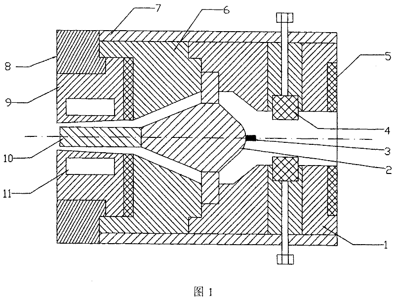
[0024] According to the φ20mm magnesium alloy to be prepared, the diameter of the outlet end of the cavity of the sizing die is selected to be 20 mm, and the taper of the sizing band of the sizing die is 1°. First, preheat the mold body and mold base of the mold to 575°C; the cooling chamber is cooled by circulating water, and the temperature of the circulating water is room temperature. After the AZ91 alloy is melted, the twin-screw mechanical stirring method is used to make semi-solid slurry. The temperature of the semi-solid slurry is 570°C. The feed temperature was also 570°C. Adjust the pore size of the flow valve to control the flow rate of the slurry to 0.2kg / s. The slurry enters the sizing die through the splitter cone to solidify to form a φ20mm rod.

Embodiment 2

[0025] Example 2: Prepare an aluminum alloy A356 pipe with an outer diameter of φ30mm and an inner diameter of φ25mm.

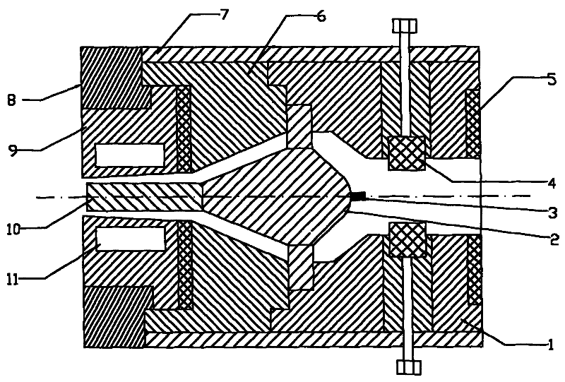
[0026] According to the aluminum alloy to be prepared with an outer diameter of φ30mm and an inner diameter of φ25mm, the diameter of the outlet end of the cavity of the sizing die is selected to be 30mm, the taper of the sizing band of the sizing die is 1°, and a mandrel of φ25mm is installed at one end of the mold splitter cone. Preheat the mold body and mold base of the mold to 608°C; the cooling chamber is cooled by circulating water, and the temperature of the circulating water is room temperature. After melting the A356 alloy, the electromagnetic stirring method was used to obtain a semi-solid slurry, and the temperature of the semi-solid slurry was 605°C. The semi-solid slurry enters the mold under the action of the piston-type pushing device, and the temperature of the semi-solid slurry at the outlet of the piston-type pushing device is also 605°C. A...


PUM


Abstract

A semi-solid forming mold and its use method. The mold is composed of a mold base, a mold body, and a sizing mold as a whole, and a cavity is formed in it. The cavity is divided into three sections, and the cavity has an inlet and an outlet; There is a splitter cone in the connecting section between the cavity of the mold base section and the cavity of the mold body section. The splitter cone is composed of the main body of the splitter cone and the smooth head of the splitter cone. The main body of the splitter cone is located in the cavity of the mold body section. Among them, the smooth head of the splitter cone is located in the rear cavity of the cavity of the mold base; the cavity of the sizing mold segment is cylindrical with a taper of 0 to 3°, and the taper is > 0; between the mold base and the mold A heater is installed on the body; a cooling chamber is installed in the sizing die. A core rod may be provided in the cavity of the sizing die section. The semi-solid slurry propulsion device is used to push the semi-solid slurry of magnesium and aluminum alloy into the mold and gradually solidify, finally forming bars and profiles of different specifications. Compared with the traditional hot extrusion method, this method has the characteristics of short processing process, low energy consumption, high efficiency and wide application range.

Description

technical field [0001] The invention relates to a method and a mold structure for preparing magnesium and aluminum alloy rods and profiles by using a semi-solid forming process, and belongs to the field of nonferrous metal preparation and processing. Background technique [0002] At present, the production of magnesium and aluminum alloy bars and profiles mainly adopts hot extrusion process. In this process, magnesium alloy ingots are prepared first, and then the ingots are processed to the required size, and then heated to an appropriate temperature range for extrusion. The extrusion die used can be divided into flat die, cone die, flat cone die, etc. according to the cross-sectional shape of the compression zone of the die hole, and can be divided into single-hole die and multi-hole die according to the number of die holes, and can be divided into integral die and split die according to the die structure. mold, shunt mold, etc. Different mold structures have the same wor...

Claims


Application Information

Patent Timeline
Patent Type & Authority Patents(China)
IPC IPC(8): B22D11/14
Inventor 杨必成徐骏张少明石力开张志峰田战峰
Owner 有研金属复材技术有限公司
Why Eureka
Try Eureka