Force compensation method for keying head of full-automatic wire keying machine

A wire bonding machine and wire bonding technology, applied in semiconductor devices, electrical components, circuits, etc., can solve the problem of contact detection failure between the bonding head and the chip surface, large impact between the bonding head and the chip surface, and reduce dynamics characteristics and other problems, to solve the problem of detection failure, improve the consistency of arc and welding quality, and suppress the impact force

Inactive Publication Date: 2010-07-14
THE 45TH RES INST OF CETC
View PDF0 Cites 0 Cited by
  • Summary
  • Abstract
  • Description
  • Claims
  • Application Information

AI Technical Summary

Problems solved by technology

However, the linear motor of the wire bonding table, especially the motor of the bonding head, due to the influence of gravity, friction, uneven preload of the guide rail, and the processing and installation errors of the mechanical structure, the nonlinear resultant force is reduced on the one hand. On the other hand, the resulting overshoot will also lead to frequent failures in contact detection between the bonding head and the chip surface, and even lead to excessive impact between the bonding head rivet and the chip surface. Large, causing damage to the chip material

Method used


Image

  • Force compensation method for keying head of full-automatic wire keying machine
  • Force compensation method for keying head of full-automatic wire keying machine
  • Force compensation method for keying head of full-automatic wire keying machine

Examples


Embodiment Construction

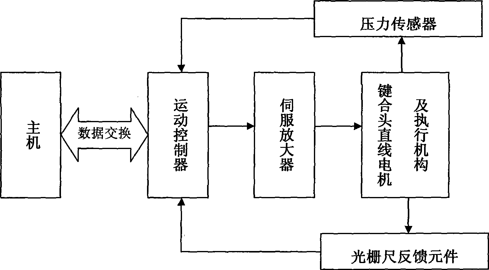
[0022] Such as figure 1 As shown, the motion control system of the automatic wire bonding machine is composed of the host, motion controller, servo amplifier, grating scale feedback element, bonding head linear motor and actuator, pressure sensor and other parts. Based on the force / position hybrid control algorithm, the main engine and the motion controller respectively realize the position closed-loop and force / acceleration closed-loop control of the linear motor of the bonding head and the actuator through the grating ruler and the pressure sensor.

[0023] When adjusting the motion parameters of each servo axis motor of the fully automatic bonding machine, the host reads the status of the slave from the data exchange memory of the motion controller DSP, judges whether all previous motion commands are completed, and MotionDone() runs in a loop until until the exercise is complete. The servo calculation cycle in the DSP of the motion controller first calls the encoder readi...


PUM


Abstract

The invention relates to a force compensation method for a bonding head of a full-automatic lead bonding machine. The method comprises the specific steps as follows: (1), a main unit and a motion controller of a motion-control system are used for controlling the uniform motion of a bonding head motor while recording and interpreting the control-output values into a discrete data group; (2), more than fifty reading values obtained from the main unit are recorded so as to draw a corresponding DA / position scatter diagram on two-dimensional coordinate plane, and the least square method is used for finding a function that is best matched with the DA / position data group through calculating sum of squares of least errors; (3), a position-force compensation table is produced following discretization of the fitted function, and the motion controller gives compensation to output force control variables or the control output values through table look-up. The method can apparently improve the dynamic characteristics of the bonding head motor for motion of welding wires, avoid overshoot by reducing the following errors of the bonding head, and apparently improve the cross-connecting field consistency of the welding wires and the welding quality.

Description

technical field [0001] The invention relates to a force compensation method for a bonding head of a fully automatic wire bonding machine. Background technique [0002] In the post-packaging field of semiconductor devices, after the diced and thinned semiconductor grains are fixed on the metal frame through the bonding (die bonding) process, it is necessary to connect the electrodes on the chip to the corresponding frame pins with conductive materials. Connection, that is, bonding process. The traditional manual gold wire (or aluminum wire, copper wire, etc.) wire bonding machine manually completes the interconnection of silicon wafers and pins of semiconductor devices under manual operation, which is not only time-consuming and inefficient, but its limited accuracy cannot meet the new requirements. Devices require arc consistency and welding quality, and the labor cost is high. Long-term engagement in this labor will also adversely affect the shoulders, elbows and eyesight ...

Claims


Application Information

Patent Timeline
Patent Type & Authority Patents(China)
IPC IPC(8): H01L21/60
CPCH01L2224/78301H01L24/78H01L2924/00014H01L2224/78H01L2224/48H01L2924/00012
Inventor 郑轩高军李吉郭强生
Owner THE 45TH RES INST OF CETC
Why Eureka
Try Eureka