
Recording type compact disc production line

A production line and optical disc technology, applied in the direction of optical record carrier, optical record carrier manufacturing, etc., can solve the problems of complex production line structure, large footprint, deformation of optical disc substrate, etc.

Inactive Publication Date: 2009-02-25
广东粤华磁电实业有限公司
View PDF0 Cites 8 Cited by
  • Summary
  • Abstract
  • Description
  • Claims
  • Application Information

AI Technical Summary

Problems solved by technology

Although this cooling device can realize the cooling of the optical disc substrate, the optical disc substrate is easily deformed during the cooling process, and a large number of defective products and waste products will be produced. , and then from vertical placement to horizontal placement and flipping process, which increases the probability of disc substrate deformation
[0005] Generally speaking, during the entire production process of the existing recordable optical disc production line, the optical disc substrate needs to go through the process of changing the position from horizontal to vertical and then from vertical to horizontal for many times. Finishing on one plane requires a large number of turning robots. On the one hand, the production line has a complex structure and a large volume, which not only requires high manufacturing costs, but also occupies a large area; on the other hand, the production line has a high failure rate and the disc substrate is prone to deformation. generate more waste

Method used


Image

  • Recording type compact disc production line
  • Recording type compact disc production line
  • Recording type compact disc production line

Examples


Embodiment Construction

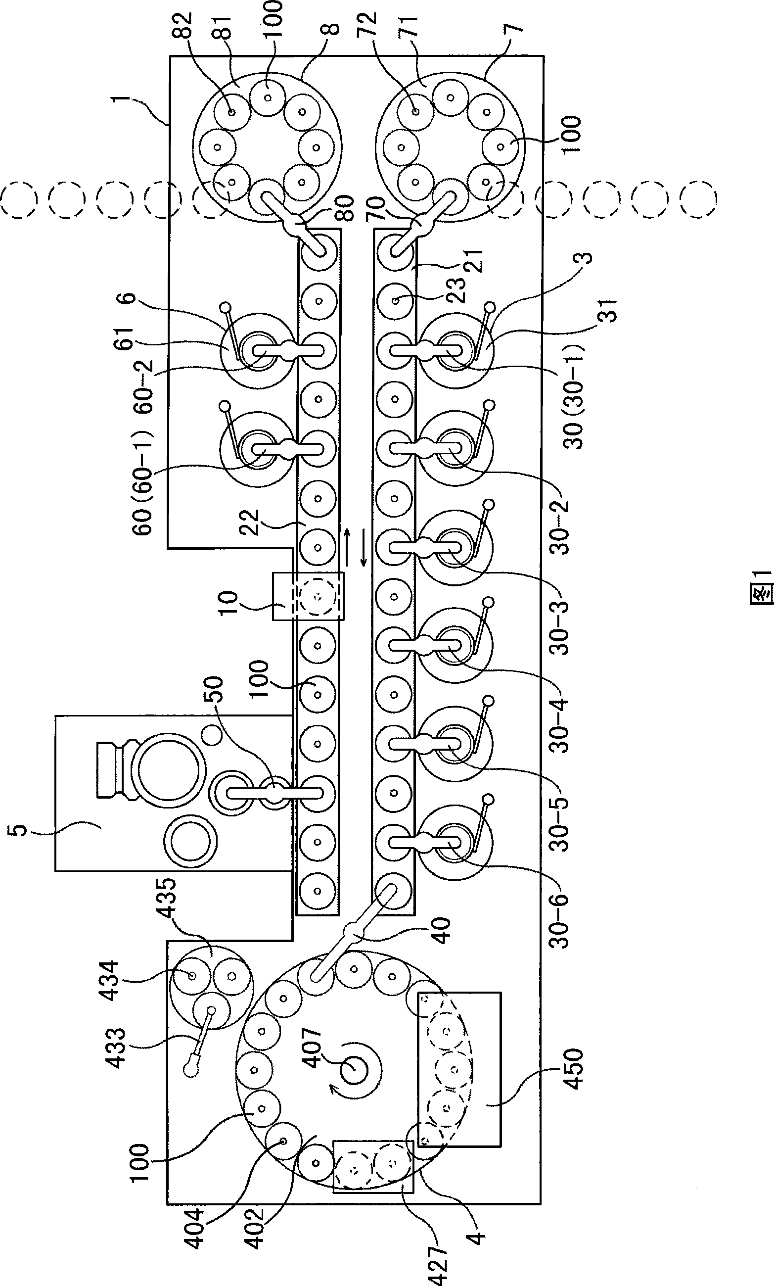
[0045]As shown in FIG. 1 , this recordable optical disc production line includes a frame 1 on which a conveyor belt is arranged. In this embodiment, the conveyor belt includes two conveyor belt sections 21, 22, each of which is composed of a driving pulley, a driven pulley and a transmission belt, and the conveyor belt sections 21, 22 are synchronous gears. shaped belt, the front end of the latter conveyor belt section 22 is continuous with the rear end of the previous conveyor belt section 21, the previous conveyor belt section 21 and the latter conveyor belt section 22 are parallel to each other and arranged side by side, and the latter conveyor belt section 22 transports the optical disc substrate The direction of the sheet 100 is opposite to the previous conveyor belt section 21 (direction as shown by the arrow in Figure 1); the transmission belt is provided with a plurality of disc substrate placement seats 23, and the disc substrate placement seats 23 on each transmission...


PUM


Abstract

A recordable compact disc production line comprises a frame, a conveying belt arranged on the frame, and a dye spin-coating device, an oven-drying device, a sputtering device and an edge washing device which are sequentially arranged on the frame from front to back along the compact disc substrate conveying direction of the conveying belt, wherein a disc feeding mechanism is arranged on the frame in a position corresponding to the front end of the conveying belt; a disc collection mechanism is arranged on the frame in a position corresponding to the rear end of the conveying belt; the support surface of a compact disc substrate base on the conveying belt on the work surface of the conveying belt is in the horizontal direction; the oven-drying device includes an oven-drying rotary table; and the support surface of a second compact disc substrate base on the oven-drying rotary table is in the horizontal direction. In each procedure, the compact disc substrate is always in the horizontal direction without inverting. On one hand, the recordable compact disc production line has the advantages of simpler and compacter structure, lowered manufacture cost and reduced occupied area. On other hand, the recordable compact disc production line can reduce the fault rate and the deformation probability of the compact disc substrate, thereby ensuring normal production and effectively preventing deformation of the compact disc substrate.

Description

technical field [0001] The invention relates to equipment for manufacturing optical discs, in particular to a recordable optical disc production line. Background technique [0002] Common recordable discs mainly include CD-R recordable discs and DVD-R recordable discs. The production process of a recordable optical disc usually includes the following steps: firstly, the optical disc substrate is produced by a forming mold; then the optical disc substrate is cooled by a cooling device; dye spin coating is performed by a dye spin coating device to form a dye layer; The dye layer spin-coated on the disc substrate is dried by the drying device, the solvent in it is volatilized, and the dye layer is dried and solidified to form a recording layer on the disc substrate; A reflective layer is formed on the disc substrate; then, the dye outside the sputtering range on the disc substrate is removed by an edge washing device. If the CD-R recordable disc is produced, after the edge sc...

Claims


Application Information

Patent Timeline
IPC IPC(8): G11B7/26
Inventor 马钦训马腾迅
Owner 广东粤华磁电实业有限公司
Learn More