
Vacuum switch contact

A vacuum switch and contact technology, applied in the electrical field, can solve the problems of low withstand voltage, concentrated electric field, large re-ignition, etc., and achieve the effects of improving the breaking current capacity, improving the high voltage resistance capacity, and reducing the arc voltage.

Inactive Publication Date: 2009-02-04
韩玉杰
View PDF0 Cites 2 Cited by
  • Summary
  • Abstract
  • Description
  • Claims
  • Application Information

AI Technical Summary

Problems solved by technology

[0006] However, the current structure of the vacuum switch contact still has problems such as the concentration of the electric field generated during the high-voltage breaking, the low voltage withstand capacity, and the possibility of re-ignition, which cannot meet the needs of higher voltage lines.

Method used


Image

  • Vacuum switch contact
  • Vacuum switch contact
  • Vacuum switch contact

Examples


Embodiment Construction

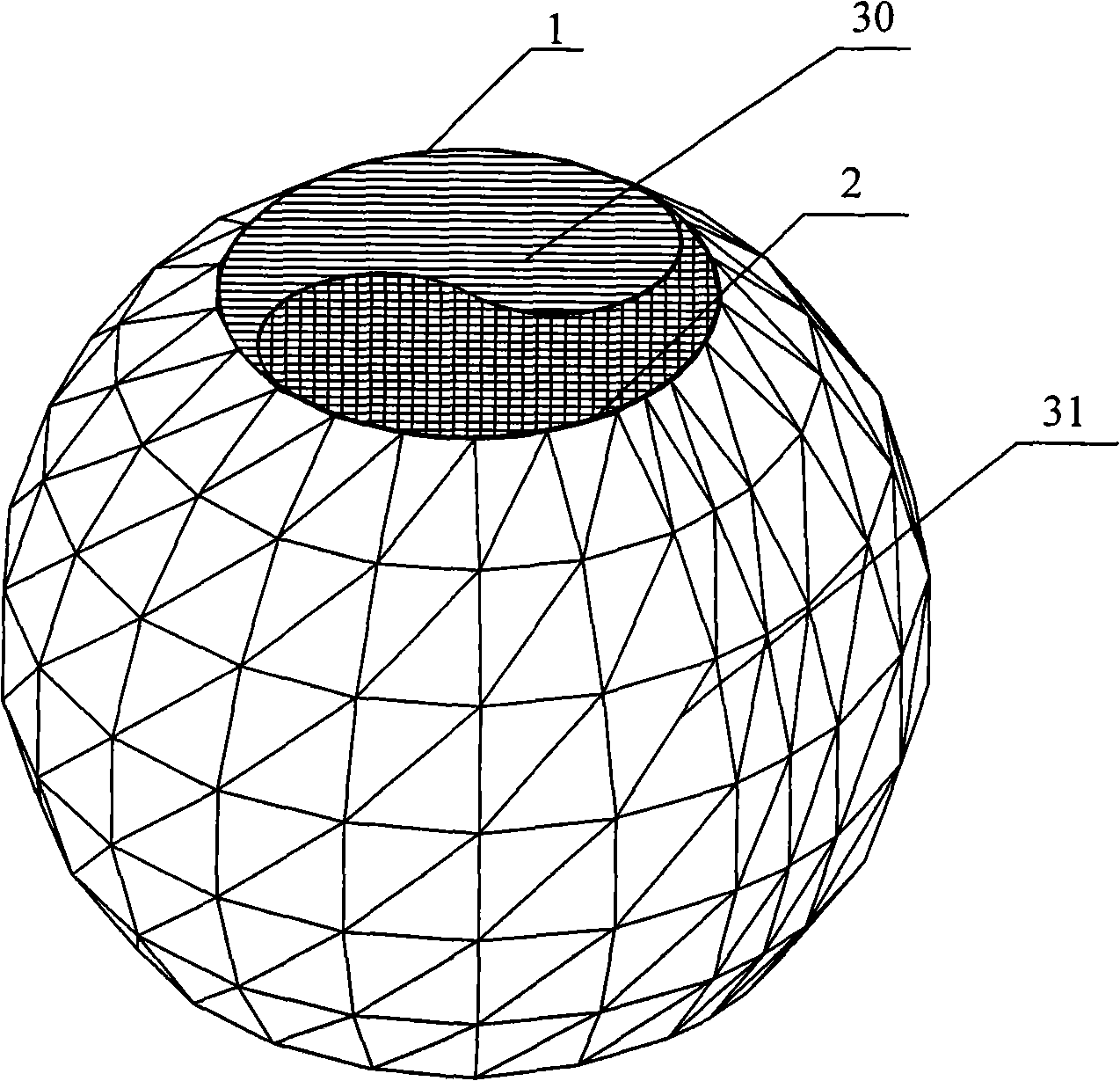
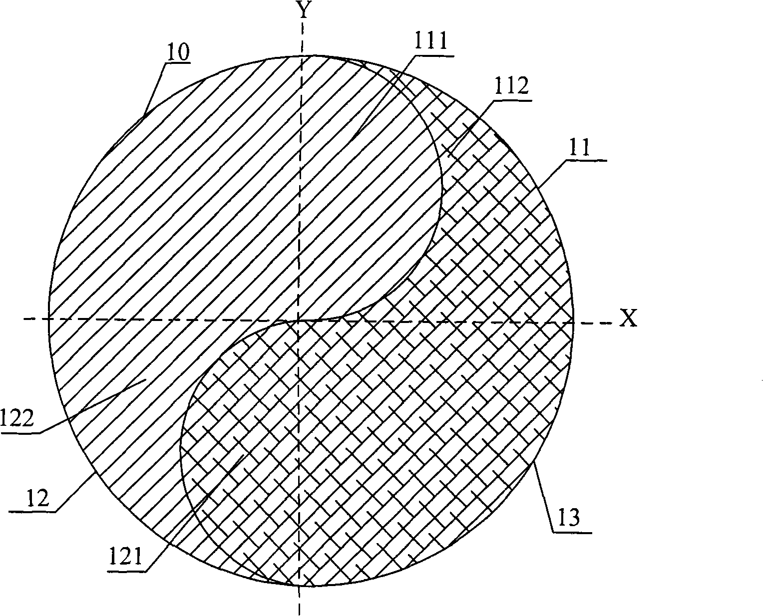
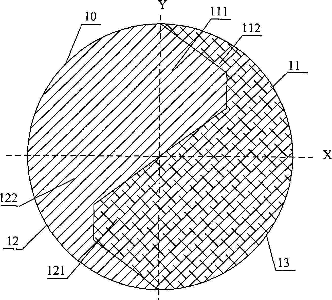
[0033] The invention provides a vacuum switch contact. During use, a rotating magnetic force line is formed between the contact surfaces of two opposite vacuum switch contacts, which can effectively improve the breaking current and high voltage resistance of the vacuum switch contact. Capability, can be applied to the vacuum switch tube in high voltage power equipment. Specifically, the embodiment of the present invention provides a vacuum switch contact with a new structure, including a contact body composed of conductive parts and magnetic permeable parts extending in the same direction and adjacent to each other, and the contact body has arc-shaped sides Surface spheroids.

[0034] Such as figure 1 As shown, it is a structural schematic diagram of Embodiment 1 of the vacuum switch contact of the present invention. This embodiment includes a conductive part 1 and a magnetically conductive part 2, the conductive part 1 and the magnetically conductive part 2 extend in the sa...


PUM


Abstract

The invention discloses a vacuum switch contact, comprising an electric conduction assembly and a magnetic conduction assembly which extend along the same direction and are in abuttal joint with each other, making up the main body of the contact. An arced spheroidal body is arranged at the lateral surface of the main body of the contact and a contact interface used to contact with another vacuum switch contact is arranged at the surface of the spheroidal body. Revolving magnetic lines of force can be formed between the contact interfaces of two opposite vacuum switch contacts, thus increasing current disjunction and high voltage tolerance of the vacuum switch contact. The vacuum switch contact is applicable on a vacuum switch contact with higher voltage circuit and can improve the high voltage disjunction capability of the vacuum switch tube.

Description

technical field [0001] The invention relates to electrical technology, in particular to vacuum switch contacts in vacuum switch tubes of power equipment. Background technique [0002] Switching equipment is widely used in various circuits, and it plays the role of closing and breaking circuits. In the process of breaking the contacts of the switchgear, an arc will be generated, and the plasma arc with the arc column as the cone surface will be generated from the cathode spot combustion, especially in the high-voltage circuit, the arc generated by the switch is particularly strong. [0003] In the closed state of the switch, the switchgear should have a low resistance, allow the rated current to pass through, and not generate excessive temperature; and in the process of breaking the switch contacts, arc extinguishing is required to break the switch contacts decisive. Existing switchgear generally uses such as oil, sulfur hexafluoride, air, semiconductor or vacuum for arc ex...

Claims


Application Information

Patent Timeline
IPC IPC(8): H01H33/664H01H33/18H01H1/06
Inventor 韩玉杰
Owner 韩玉杰
Learn More