
Auditory localization wireless measurement method

A technology of sound source localization and wireless measurement, which is applied in the direction of radio wave measurement system, positioning, measurement device, etc., to achieve the effect of ensuring real-time performance and accuracy, overcoming the influence of various factors, and convenient layout

Active Publication Date: 2009-01-07
TSINGHUA UNIV
View PDF0 Cites 35 Cited by
  • Summary
  • Abstract
  • Description
  • Claims
  • Application Information

AI Technical Summary

Problems solved by technology

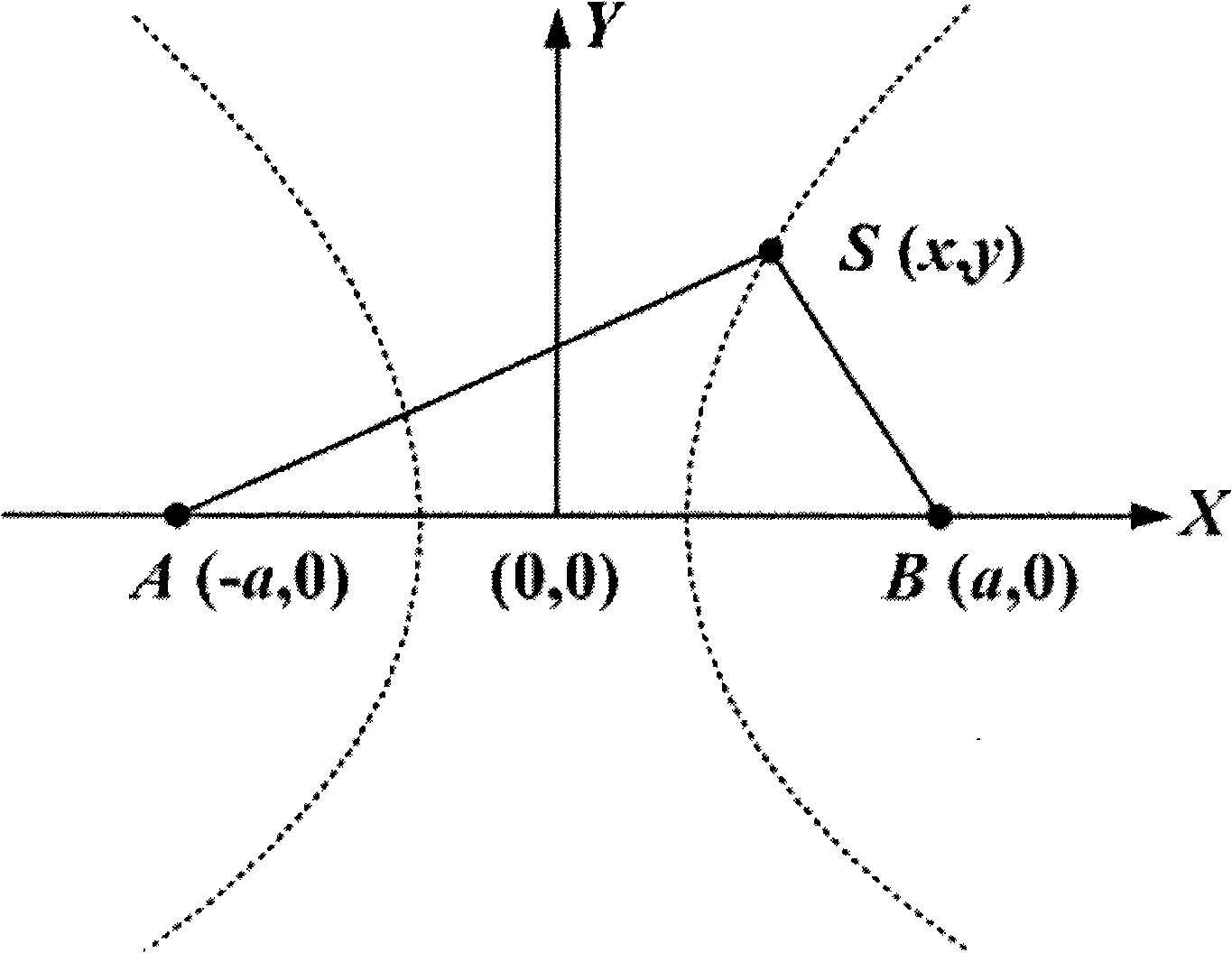
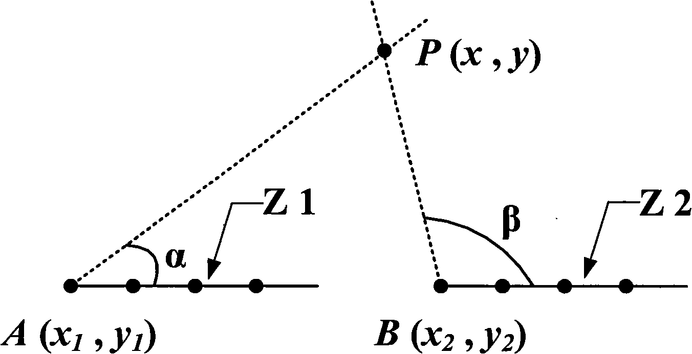
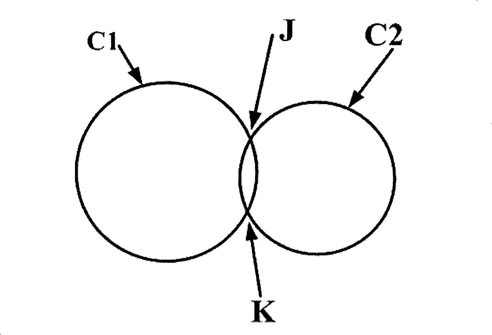
[0015] The purpose of the present invention is to propose a wireless measurement method for sound source localization based on wireless sound sensors. The technical solution is to use the received signal energy localization method for sound source localization, and to measure the sound signal sent by the target through a plurality of wireless sound sensors. , and according to the measured sound signal strength, select the most suitable sensors to participate in sound source location, and use the method of received signal energy to perform sound source location. In order to overcome the influence of noise and medium non-uniformity and improve the positioning accuracy, the equation group The solution problem is transformed into an optimization problem, and the steepest descent method is used to search for the position of the sound source to realize the location of the sound source. The specific steps are as follows:

Method used


Image

  • Auditory localization wireless measurement method
  • Auditory localization wireless measurement method
  • Auditory localization wireless measurement method

Examples


Embodiment Construction

[0036] Specific embodiments of the present invention are further described as follows:

[0037] Step (1) Set up the wireless sound sensor and set its signal amplitude threshold. The wireless acoustic sensor used in the present invention includes a sensor module, an A / D conversion module, a memory module, a processor module, a wireless communication module and a power supply module. The sensor module includes a sound sensor based on micro-electromechanical technology; the analog signal output by the sound sensor can be converted into a digital signal that can be processed by the processor through the A / D conversion module. The memory includes random access memory RAM and read-only memory ROM for storing data and corresponding processing programs. The processor module consists of a microprocessor responsible for such tasks as threshold judgment, sound sensor activation, filtering and energy calculation. The wireless communication module is responsible for communication with th...


PUM


Abstract

The invention belongs to the fields of measurement and wireless communication, disclosing a sound localization-based wireless measuring method. Firstly, a plurality of wireless acoustic sensors are arranged in a designated area; the coordinates of the sensors are confirmed, and one of the wireless sensors is used as a data aggregation and processing point; a positioning method by means of receiving a signal energy is adopted to localize the sound; a plurality of wireless acoustic sensors are used for measuring a sound signal sent by a target; and a plurality of the most suitable sensors are selected to participate into the sound localization according to a measured sound signal intensity so as to localize the sound by the positioning method by means of receiving the signal energy. In order to overcome the influence of noise and heterogeneity of a medium and to improve positioning accuracy, the problem of an equation set solution is changed into an optimization problem; and a steepest descent method is adopted to search the location of the sound so as to realize the sound localization. A sound localization system established by the invention has the advantages of convenient arrangement and strong adaptability, thereby especially being applied to the positioning of a military vehicle in an outdoor battlefield and an occasion such as an emergency treatment.

Description

technical field [0001] The invention belongs to the field of measurement and wireless communication, and relates to sound measurement technology, sound source location technology and wireless communication technology, in particular to a wireless measurement method for two-dimensional planar sound source location based on wireless sound sensors. Background technique [0002] Sound source localization refers to estimating the spatial position of the sound source at a certain moment based on the sound information measured by the sound sensor. According to the different physical quantities of signal measurement, the current sound source localization technology is mainly divided into three categories, namely time difference of arrival localization, direction of arrival localization and received signal energy localization. Various localization methods generally assume that the sound source is isotropic, that is, it is considered that the propagation of sound waves from the sound s...

Claims


Application Information

Patent Timeline
IPC IPC(8): G01S5/18
Inventor 王雪毕道伟王晟丁梁
Owner TSINGHUA UNIV
Learn More