Portable fuel cell system
A fuel cell system and portable technology, applied in the direction of fuel cells, fuel cell additives, fuel cell grouping, etc., can solve problems such as inconvenient use and portability, complicated process, uncontrollable hydrogen production speed, etc.
- Summary
- Abstract
- Description
- Claims
- Application Information
AI Technical Summary
Problems solved by technology
Method used
Image
Examples
Embodiment 1
[0051] When using proton exchange membrane fuel cells to generate electricity (such as Figure 5 shown),
[0052] 1. Establish a standby state
[0053] (1) In the initial state, V1-V5 are in the closed state, and the cover of the fuel inlet 8 is closed.
[0054] (2) Open the lid of the fuel inlet and inject sodium borohydride, sodium hydroxide and water. The weight percentage of each component is 50% sodium borohydride, 15% sodium hydroxide, and the rest is pure water. Then screw on the cap. The feed port is made of 316 stainless steel corrosion-resistant material and sealed with a tapered thread.
[0055] (3) Open V1-V4 so that the fuel enters the hydrogen generating reactor by static pressure, and then close V2-V4 in turn. Thus, the initial working state of the fuel cell system is established.
[0056] 2. Operating status
[0057] (1) Turn on V3 to introduce hydrogen into the fuel cell.
[0058] (2) Open V1 and V2, so that the fuel enters the hydrogen generating react...
Embodiment 2
[0069] When anion exchange membrane fuel cells are used to generate electricity (such as Image 6 shown),
[0070] 1. Establish a standby state
[0071] (1) Initial state: V1-V5 are in the closed state, and the fuel inlet cover is closed.
[0072] (2) Open the lid of the fuel inlet and inject sodium borohydride, sodium hydroxide and water. The weight percentages of each component are 35% sodium borohydride, 15% sodium hydroxide, and the rest are pure water. Then screw on the cap. The feed port is made of 316 stainless steel corrosion-resistant material and sealed with a tapered thread.
[0073] (3) Open V1-V4 so that the fuel enters the hydrogen generating reactor by static pressure, and then close V2-V4 in turn. Thus, the initial working state of the fuel cell system is established.
[0074] 2. Operating status: (1) Turn on V3 to introduce hydrogen into the fuel cell.
[0075] (2) Open V1 and V2, so that the fuel enters the hydrogen generating reactor by pressure differ...
Embodiment 3
[0084] Embodiment 3: basically the same as Example 2
[0085] The weight percent of each component of the fuel is 25% of sodium borohydride, 10% of sodium hydroxide, and the rest is pure water.
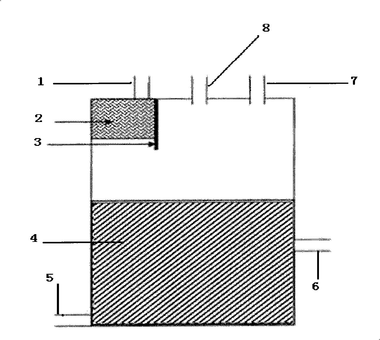
[0086] In this example invention, the fuel tank is made of nickel-plated stainless steel plate material, and the specific structure is as follows figure 1 As shown, there are feed inlet 8, waste discharge outlet 5, hydrogen outlet 7, hydrogen generation product inlet 1 and sodium borohydride solution outlet 6 leading to the reactor. A gas-liquid separation device is provided at the inlet of the hydrogen generation product, consisting of a baffle 3 and a porous material. The baffle is made of fluorine plastic coated stainless steel plate. The fuel tank and the hydrogen generating reactor are connected by two one-way needle valves. 2 is a porous material, and the porous material is foamed nickel.
[0087] In the invention of this example, the hydrogen generation reactor exhausts air...
PUM
| Property | Measurement | Unit |
|---|---|---|
| pore size | aaaaa | aaaaa |
Abstract
Description
Claims
Application Information
 - Generate Ideas
- Intellectual Property
- Life Sciences
- Materials
- Tech Scout
- Unparalleled Data Quality
- Higher Quality Content
- 60% Fewer Hallucinations
Browse by: Latest US Patents, China's latest patents, Technical Efficacy Thesaurus, Application Domain, Technology Topic, Popular Technical Reports.
© 2025 PatSnap. All rights reserved.Legal|Privacy policy|Modern Slavery Act Transparency Statement|Sitemap|About US| Contact US: help@patsnap.com


