Sampling mixer and receiver
A mixer and capacitor technology, applied to electrical components, transmission systems, modulation transfer, etc., to achieve the effect of reducing quantization noise and reducing current consumption
Inactive Publication Date: 2008-11-26
PANASONIC CORP
View PDF3 Cites 0 Cited by
- Summary
- Abstract
- Description
- Claims
- Application Information
AI Technical Summary
Problems solved by technology
Also, since the rotating capacitors 7 to 14 are sequentially connected to the history capacitor 6, the in-phase sampling mixer 2 brings about an IIR (Infinite Impulse Response) filter effect
Method used
View moreImage
Smart ImageViewing Examples
Examples
Embodiment 1
Embodiment 2
Embodiment 3
Login to View More PUM
 Abstract
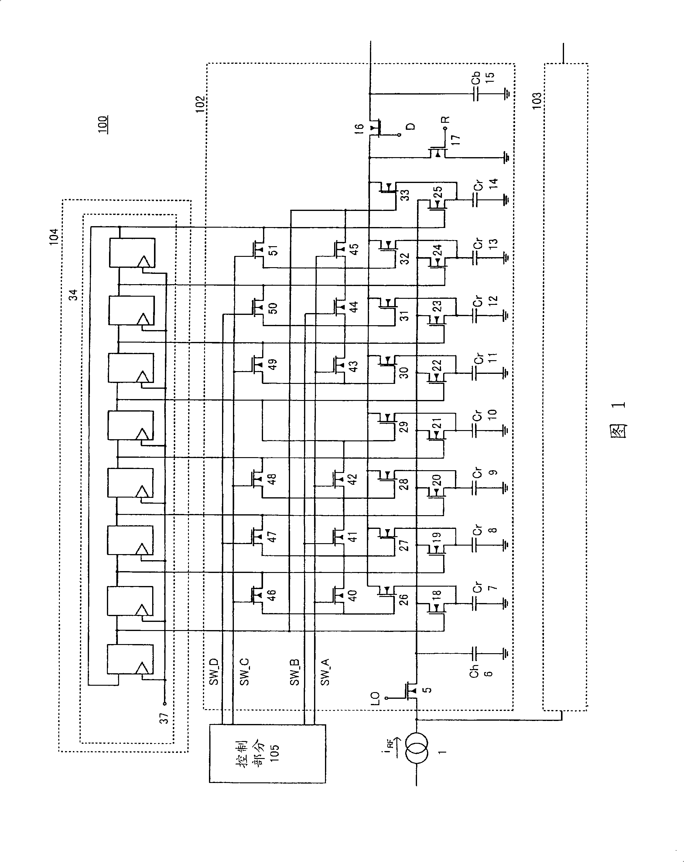
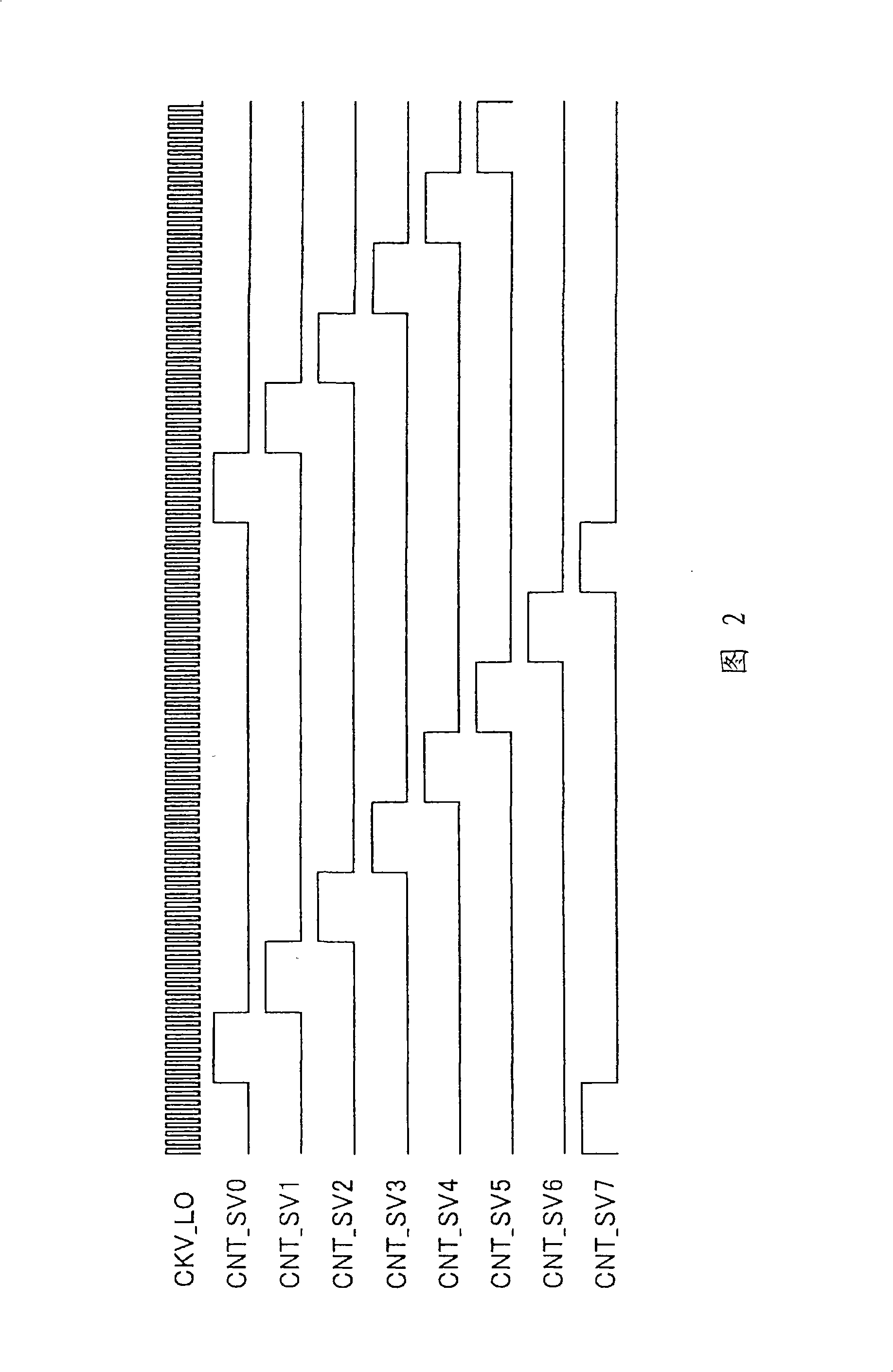
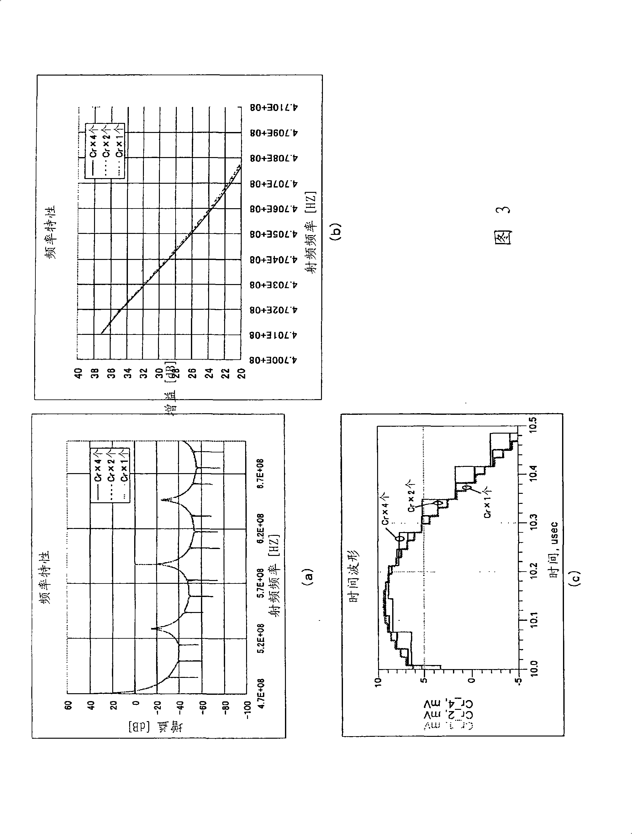
A receiver and a sampling mixer capable of optimizing the sampling rate of an output signal in accordance with the band ratio of a modulation band to the RF frequency of a received signal. A sampling mixer comprises a history capacitor (6) that integrates input signals current-converted for a continuous time interval; rotation capacitors (7-14) that repeat the integration and discharging of the input signals; a digital control (104) that controls the integration intervals of the rotation capacitors (7-14); and a control part (105) that controls the discharging of the rotation capacitors (7-14). In the sampling mixer, the number of ones of the rotation capacitors (7-14) that are simultaneously connected to a buffer capacitor (15) is changed in accordance with the band ratio of the modulation band to the RF frequency. In this way, the decimation ratio is made variable, whereby the quantized noise during the A / D conversion can be reduced.
Description
Sample Mixers and Receivers technical field The present invention relates to sampling mixers and receivers with variable decimation ratios for use in radio circuits of radio communication equipment, such as mobile communication systems, for converting signals into temporally discrete signals, For frequency conversion and filtering. Background technique As a conventional mixer, as described in Patent Document 1, there is a mixer that samples a current conversion signal and produces a filter effect by a switched capacitor circuit. FIG. 8 is a circuit diagram of a sampling mixer set forth in Patent Document 1 of the prior art. In Fig. 8, sampling mixer 800 includes: transconductance (transconductance) amplifier (TA) 1, in order to convert the radio frequency (RF) that receives is electric current; In-phase sampling mixing part 2, in order to sample the RF current signal output from TA ; the anti-phase sampling mixing part 3; and the digital control part 4, which is used to...
Claims
Login to View More Application Information
Patent Timeline
 IPC IPC(8): H03D7/00H04B1/26
CPCH03D7/125H03D2200/006
Inventor 细川嘉史松冈昭彦宫野谦太郎
Owner PANASONIC CORP
- R&D Engineer
- R&D Manager
- IP Professional
- Industry Leading Data Capabilities
- Powerful AI technology
- Patent DNA Extraction
Learn More Browse by: Latest US Patents, China's latest patents, Technical Efficacy Thesaurus, Application Domain, Technology Topic, Popular Technical Reports.
© 2024 PatSnap. All rights reserved.Legal|Privacy policy|Modern Slavery Act Transparency Statement|Sitemap|About US| Contact US: help@patsnap.com


