Eureka AIR delivers breakthrough ideas for toughest innovation challenges, trusted by R&D personnel around the world.

Method of preparing corrosive thermal insulation anti-ablation composite coating on light alloy surface

A composite coating and light alloy technology, which is applied to the device for coating liquid on the surface, anti-corrosion coating, coating, etc., can solve the problems of poor bonding force, poor heat resistance performance, difficult control of coating quality and thickness, etc.

Inactive Publication Date: 2008-11-19
HARBIN INST OF TECH
View PDF0 Cites 12 Cited by
  • Summary
  • Abstract
  • Description
  • Claims
  • Application Information

AI Technical Summary

Problems solved by technology

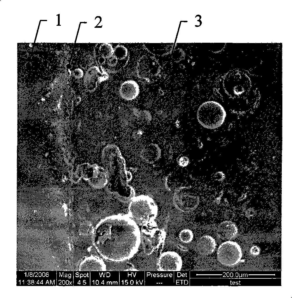
[0003] The present invention aims to solve the problem that the prepared coating has poor thermal insulation and ablation resistance, poor bonding force, easy peeling and failure, and difficult to control the coating quality and thickness in the current method for preparing a composite coating on the surface of a light alloy. To provide a method for preparing anti-corrosion, heat-insulation and anti-ablation composite coating on the surface of light alloy

Method used


Image

  • Method of preparing corrosive thermal insulation anti-ablation composite coating on light alloy surface
  • Method of preparing corrosive thermal insulation anti-ablation composite coating on light alloy surface

Examples


specific Embodiment approach 1

[0009] Specific Embodiment 1: In this embodiment, the method for preparing an anti-corrosion, heat-insulating and anti-ablation composite coating on the surface of a light alloy is carried out as follows: 1. After degreasing the surface of the light alloy, connect the positive output end of the pulse power supply to the light alloy 1. Connect the negative output terminal of the pulse power supply to the stainless steel, then put the light alloy and stainless steel into the electrolytic tank, and make the alkaline electrolyte in the electrolytic tank submerge the light alloy and stainless steel to ensure that the light alloy and stainless steel are not in the electrolytic tank Contact; 2. Turn on the power supply, control the output voltage of the pulse power supply to 400-650V, the frequency is 400-800Hz, the duty cycle is 4%-20%, the output time is 30-100min, and the temperature of the electrolyte is controlled during the power-on process Below 50°C, the surface micro-arc oxid...

specific Embodiment approach 2

[0012] Specific embodiment two: the differences between this embodiment and specific embodiment one are: in step two, the output voltage of the control pulse power supply is 450-550V, the frequency is 500-700Hz, the duty cycle is 8%-16%, the output time 50-80 minutes. Other steps and parameters are the same as those in Embodiment 1.

specific Embodiment approach 3

[0013] Embodiment 3: The differences between this embodiment and Embodiment 1 are: in step 2, the output voltage of the control pulse power supply is 500V, the frequency is 600Hz, the duty cycle is 12%, and the output time is 65min. Other steps and parameters are the same as those in Embodiment 1.


PUM

PropertyMeasurementUnit
Wire ablation rateaaaaaaaaaa
Mass ablation rateaaaaaaaaaa
Wire ablation rateaaaaaaaaaa

Abstract

The invention discloses a method for preparing a rot proof, heat proof, burn resistance and anti-corrosion composite coating on a light alloy surface, and relates to a method for preparing a composite coating on a light alloy surface. The method solves the deficiencies existing in the prior method for preparing the composite coating on the light alloy surface that the thermal protective performances, such as the heat proof and the burn resistance and the anti-corrosion performances, of the prepared coating are poor, or the binding force is poor, the coating is easy to scale off and out of work, and the quality and the thickness of the coating are difficult to be controlled. The method for preparing the rot proof, heat proof, burn resistance and anti-corrosion composite coating on the light alloy surface is performed according to the following steps: firstly, de-oiling and connecting; secondly, electrifying; thirdly; drying; fourthly, preparation of spray coating liquid; fifthly, coating and drying; sixthly, the repetitive operation of the step five, and thereby the rot proof, heat proof, burn resistance and anti-corrosion composite coating is prepared on the light alloy surface. The light alloy surface prepared on the light alloy surface has the properties of rot proof, heat proof, burn resistance and anti-corrosion, and the binding force of the coating and the basal body is high.

Description

technical field [0001] The invention relates to a method for preparing a composite coating on the surface of a light alloy. Background technique [0002] When an aerospace vehicle flies through the atmosphere, the surface temperature will rise rapidly. The mechanical properties of high-strength metals and composite materials that lead to aircraft structural materials will decline, and at the same time seriously affect the thermal environment inside the spacecraft. Therefore, heat insulation and anti-ablation measures must be taken to prevent the strength and stiffness of structural materials from being greatly lost under high temperature conditions, effectively control particle flow erosion, and ensure the normal working environment of instruments and equipment in the cabin, so that the working temperature does not exceed Or lower than the allowable range, in order to improve the reliability of the aircraft. The current methods of preparing composite coatings on the surfac...

Claims


Application Information

Patent Timeline
IPC IPC(8): B05D7/24B05D3/00C25D11/02C09D163/00C09D161/06C09D5/08
Inventor 王亚明崔艳芹欧阳家虎郭立新贾德昌周玉
Owner HARBIN INST OF TECH
Why Eureka
Eureka Blog
Learn More