
Mouthpiece device of electronic cigarette

a mouthpiece and electronic cigarette technology, applied in the field of electronic cigarettes, can solve the problems of high manufacturing cost, unsatisfactory heat insulation, and increase manufacturing cost, and achieve the effects of reducing cost, good heat insulation, and convenient manufacturing

Inactive Publication Date: 2015-06-16
HUIZHOU KIMREE TECH
View PDF8 Cites 49 Cited by
  • Summary
  • Abstract
  • Description
  • Claims
  • Application Information

AI Technical Summary

Benefits of technology

[0005]A main object of the present invention is to provide a mouthpiece device of an electronic cigarette, which facilitates manufacturing, reduces cost, and has good heat insulation.
[0017]The advantages of the present invention are that: the mouthpiece device has an integrated atomizing cup, which facilitates manufacturing and reduces cost; and the atomizing cup has good heat insulation performance; furthermore, the mouthpiece device has a filtering plate and the cap with filtering function, which render the mouthpiece device to preferably filter tobacco liquid.

Problems solved by technology

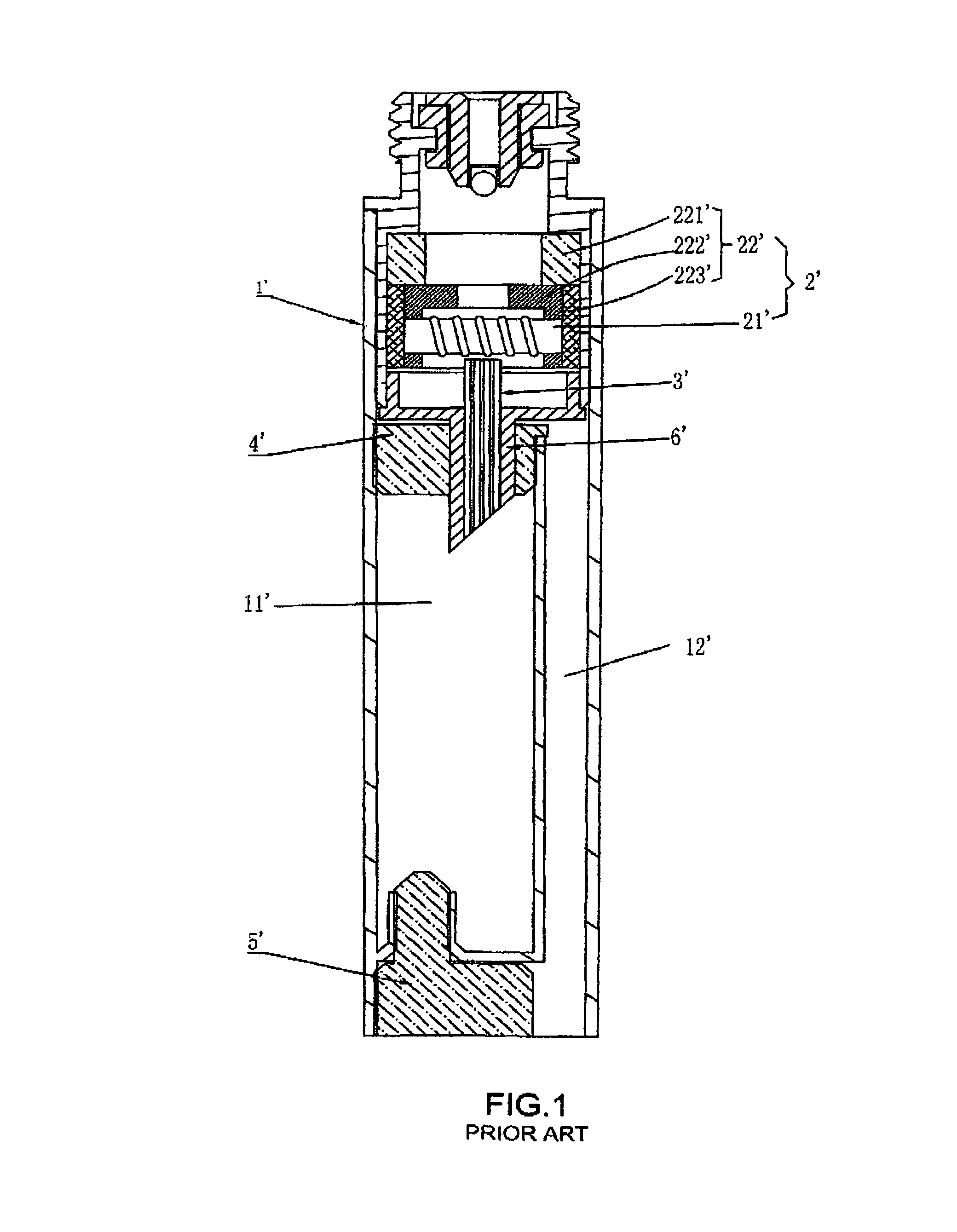
However, the existing mouthpiece device of the electronic cigarette has such disadvantages that: it is very complicated to manufacture and assemble the atomizing cup assembly 22′, the manufacturing cost is high; the ceramic seat 222′ and foam-nickel unit 223′ directly contact with an inner wall of the shell 1′ which results unsatisfactory heat insulation, therefore, the temperature at outer wall of the shell 1′ is relatively high even to be felt burning hand, and the electronic cigarette cannot be used; the metal frame 6′ does not facilitate liquid-guiding, but raises the manufacturing cost; moreover, the cap 5′ is set at an inhaling end of the shell 1′, the aerosol passage 12′ directly extends to outside of the shell 1′, therefore, tobacco particles will flow together with aerosol from the aerosol passage 12′ to outside of the shell 1′, and thus fail to be filtered.

Method used


Image

  • Mouthpiece device of electronic cigarette
  • Mouthpiece device of electronic cigarette
  • Mouthpiece device of electronic cigarette

Examples


Embodiment Construction

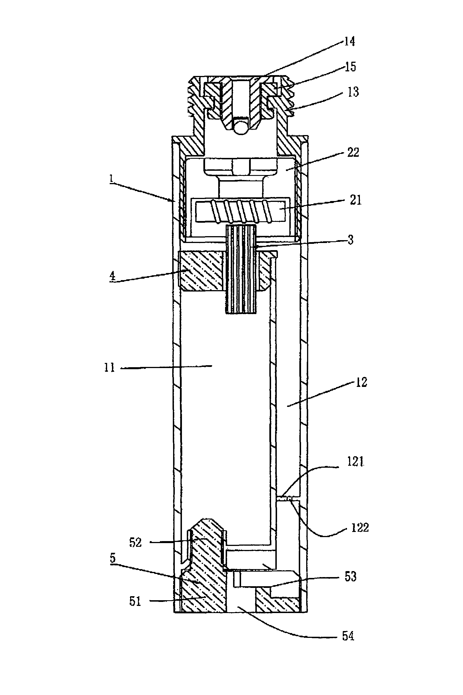
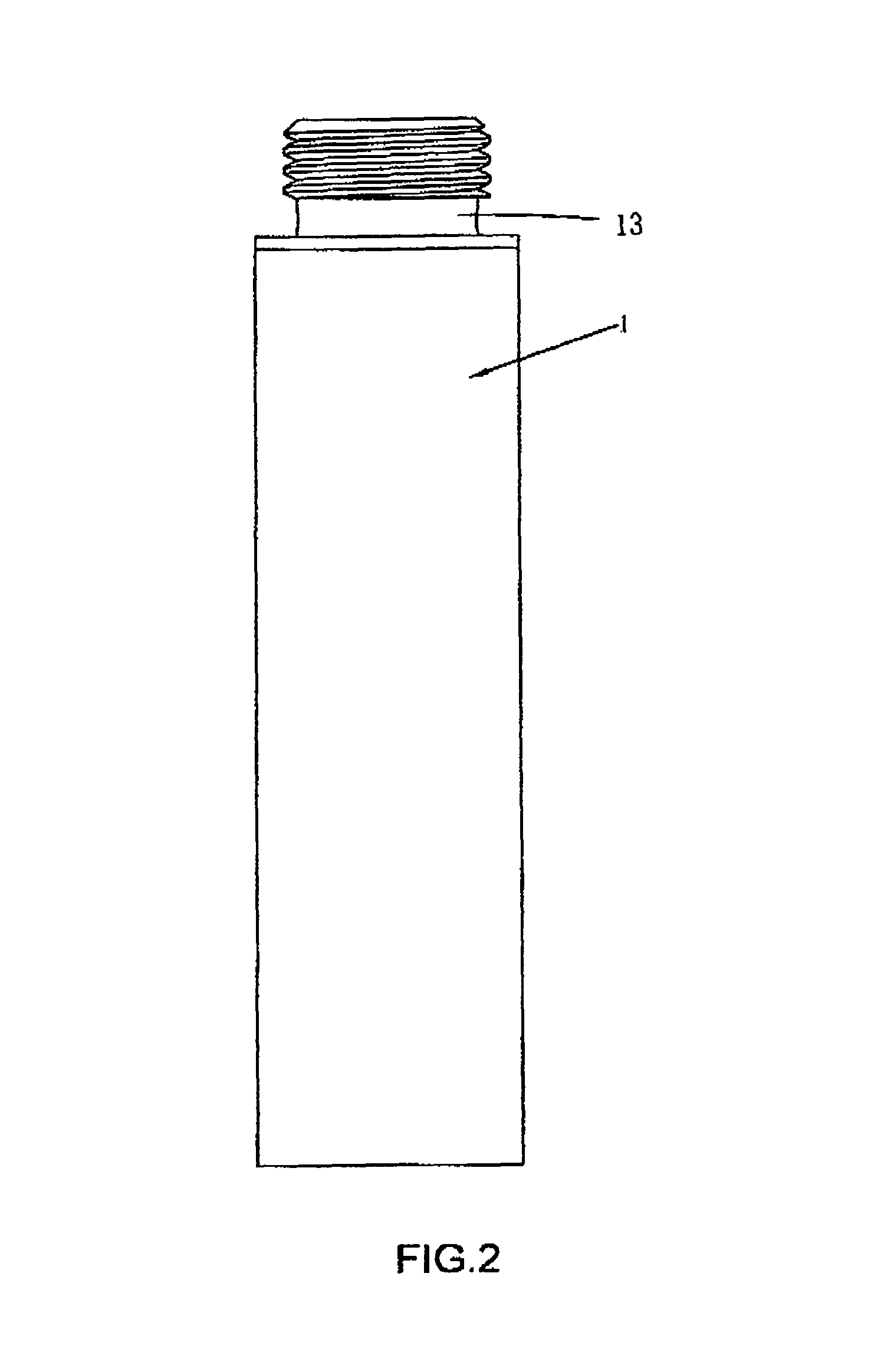
[0027]Referring to FIGS. 2-8, the present invention provides a mouthpiece device of an electronic cigarette and a filtering device thereof. The mouthpiece device comprises an inhaling shell 1 with two open ends, an atomizing device 2, a liquid-guiding tube 3, a stopper 4, and the filtering device which has a cap 5 or cap 5″. One of the open end of the inhaling shell 1 is used as a connecting end for connection with a power supply part of the electronic cigarette, and the other open end is used as an inhaling end for user's suction and is covered with the cap 5 or 5″.

[0028]The inhaling shell 1 comprises a liquid reservoir 11, an aerosol passage 12 alongside the liquid reservoir 11, a connection element 13, an electrode element 14, and an insulating ring 15. The liquid reservoir 11 and the aerosol passage 12 are longitudinally set in the shell 1. The first ends as inner ends of both the liquid reservoir 11 and the aerosol passage 12 are open side by side and facing the atomizing devic...


PUM


Abstract

The present invention relates to a mouthpiece device of an electronic cigarette, including an atomizing device for vaporizing tobacco liquid into aerosol and a liquid reservoir for storing tobacco liquid in an inhaling shell. The atomizing device includes an atomizing cup with an atomizing chamber, and an atomizer held in the atomizing chamber. The atomizing cup is molded by an integrated process. The mouthpiece device further includes a cap at an end of the liquid reservoir, and an aerosol passage therein: The cap defines a stepped slot for filtering tobacco particles in aerosol. The stepped slot is communicated with the aerosol passage. The present invention mainly solves such problems of the existing mouthpiece device as complicated manufacturing, high cost, bad heat insulation, and failing to filter tobacco particles; and obtains a mouthpiece device with simple manufacturing, lower cost, good heat insulation and better effectiveness of filtering tobacco particles.

Description

BACKGROUND OF THE INVENTION[0001]The present invention relates to an electronic cigarette, especially to a mouthpiece device of the electronic cigarette.[0002]Referring to FIG. 1, mouthpiece device of the existing electronic cigarette comprises an inhaling shell 1′, atomizing device 2′, liquid-guiding tube 3′ for guiding tobacco liquid flowing therethrough, stopper 4′, and cap 5′.[0003]The shell 1′ comprises a reservoir 11′ for storing tobacco liquid therein and an aerosol passage 12′ for allowing aerosol to pass therethrough. The atomizing device 2′ comprises an atomizer 21′ and an atomizing cup assembly 22′ for holding the atomizer 21′. The atomizing cup assembly 22′ is composed of a support seat 221′, a ceramic seat 222′ and a foam-nickel unit 223′. The liquid-guiding tube 3′ has one end thereof connected with the reservoir 11′ through a metal frame 6′ so as to guide the tobacco liquid from the reservoir 11′ to the atomizing cup assembly 22′. The stopper 4′ is inserted in the res...

Claims


Application Information

Patent Timeline
Patent Type & Authority Patents(United States)
IPC IPC(8): A61M15/06A24F47/00A24D3/17A24F40/10A24F40/42A24F40/485
CPCA24F47/008A61M15/06A24D3/17A24F40/10A24F40/42A24F40/485A24F47/00A24F40/46
Inventor LIU, QIUMING
Owner HUIZHOU KIMREE TECH
Learn More