
Combustion type deferred blasting cap and deferred elements thereof

A technology of detonating detonators and detonators, which is applied in the field of delay components, can solve the problems of unreliable ignition ability and stability of delay agents, delay jumps, hidden safety hazards, etc., and achieve friendly production technology, reduced overall length, and strong adaptability Effect

Active Publication Date: 2011-06-01
UNIV OF SCI & TECH OF CHINA
View PDF0 Cites 1 Cited by
  • Summary
  • Abstract
  • Description
  • Claims
  • Application Information

AI Technical Summary

Problems solved by technology

However, from the actual use situation, the ignition ability and stability of the slow-burning delay agent are not reliable enough, and quality problems such as fire failure and delay jump often occur, which brings inconvenience to production management and even brings safety hazards.
[0004] At present, there are reports of using microelectronics technology to develop digital detonators in some foreign projects, but the cost is high, the price is expensive, and the use is limited.

Method used


Image

  • Combustion type deferred blasting cap and deferred elements thereof
  • Combustion type deferred blasting cap and deferred elements thereof
  • Combustion type deferred blasting cap and deferred elements thereof

Examples


Embodiment 1

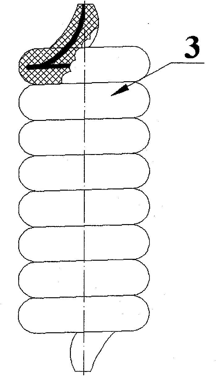
[0029] image 3 It is a detonator with detonating charge delay made of helical spring-like delay element. The shape of the helical spring-like delay element 3 used is visible figure 2, wherein the outer diameter of the extension tube used is 2.0 mm, the outer diameter of the "spring" is 5.0 mm, and the pitch is 5 turns / cm. The helical spring-like extension element 3 is fixedly connected with the detonator shell by the waist clip 5, and its upper protruding end face is about 3.0 mm away from the electric ignition charge 4 of the detonator, and the distance between the lower protruding end face and the fire transmission hole 13 of the reinforcing cap 12 is equal to 5 mm. . In actual use, after the electric ignition charge 4 is ignited, the exposed drug core on the protruding end surface of the delay element 3 is ignited immediately; Flame passes through the fire transmission hole 13 and detonates the primer 6. Under the action of the detonation wave of the priming charge 6,...

Embodiment 2

[0031] Figure 4 It is a delay electric detonator without priming charge made of helical spring delay element. The shape of the helical spring-like delay element 3 used is visible figure 2 , wherein the extension tube used has an outer diameter of 2.5 mm, a helical "spring" with an outer diameter of 6.0 mm, and a pitch of 4 turns / cm. The helical spring-like extension element is placed in the inner cap 11, and is fixedly connected with the detonator shell by the waist clip 5. The upper protruding end surface is about 5.0 mm away from the electric ignition powder head 4 of the detonator, and the lower protruding end surface is in contact with the excitation charge 10. In actual use, after the electric ignition charge 4 is ignited, the exposed drug core on the protruding end surface of the delay element 3 is ignited immediately; Ignition propellant 10. Under the combustion action of the propellant 10, a high-speed flying piece is formed at the bottom of the inner cap 11, whic...

Embodiment 3

[0033] Figure 5 It is a non-priming non-electric delay detonator made of a helical spring-like delay element in a non-priming non-electric detonator. Among them, the outer diameter of the delay tube used is 2.7 mm, and the outer diameter of the helical "spring" is 6.4 mm. The nonel tube 8 cooperates with the bayonet plug 9 to play the role of sealing the detonator and transmitting the detonation signal; the helical spring-like delay element 3 The waist card 5 is fixedly connected with the detonator shell, and its upper end face is about 2.0 mm away from the nonel 8 port, and the lower end face is in contact with the excitation charge 10 . After the detonation wave propagates to the nozzle inside the detonation tube 8, under the action of the shock wave and flame, the exposed drug core on the upper end surface of the delay element 3 is ignited; after a period of burning time, the other end surface of the delay element 3 The medicine core burns, ejects flame outwards, and igni...


PUM


Abstract

The invention pertains to the technical field of priming material and particularly relates to a combustion-type delay primer detonator and a delay component; the detonator comprises a delay electric / non-electric detonator with / without initiating explosive; a delay tube with an outer diameter of 1.0mm to 3.0mm is wound in a helical spring shape or repeatedly folded into a cylindrical delay component, with the outer diameter loose fitting and mechanically fixed with the inner diameter of the shell or an inner cap of the detonator; the two ends of the delay tube are respectively located in the center of the helical spring shape or cylindrical body and provided with a protrusion section with a length of 1.0 to 5.0 mm; the protrusion section at one end is at a distance equal to or less than 5mm from the igniting hole in the detonator or directly touches the surface of the initiating explosive, and the protrusion section at the other end is at a distance of 4.0 mm to 10.0 mm from the nozzleof the detonator or the electric fusehead; or a delay tube with an outer diameter of 1.4mm to 1.5mm is inserted into the cavity of the detonating tube; one end of the delay tube is parallel to the nozzle of the detonating tube and at a distance equal to or less than 5mm from the initiating explosive in the detonator or the surface of the initiating explosive; the other end of the delay tube is inthe detonating tube and the nozzle thereof touches the booster explosive on the inner wall of the detonating tube. The invention can realize a correct long-term delay without expending the length of the detonator and can improve the quality of the relay detonator.

Description

technical field [0001] The invention belongs to the technical field of detonating materials, and in particular relates to a combustion-type detonation delay detonator and a delay element used therein. Background technique: [0002] With the continuous development of science and technology, people put forward higher requirements for the extension length and accuracy of detonation time. At present, the more mature detonator detonation delay technology is the lead core drawing technology: the thick lead tube material with the delay drug is drawn through multiple drawing processes to become a lead that can be loosely matched between its outer diameter and the inner diameter of the detonator (usually about 7mm). Tube (usually in the range of 5.5mm ~ 6.5mm), then cut into a suitable length according to the length of the delay time is the delay element, and then put it into the detonator. This technology requires that the outer diameter of the lead tube after drawing is loosely ma...

Claims


Application Information

Patent Timeline
Patent Type & Authority Patents(China)
IPC IPC(8): F42C19/08
CPCF42B3/10
Inventor 沈兆武马宏昊
Owner UNIV OF SCI & TECH OF CHINA
Learn More