
Tooth thickness variable cylinder profile modified gear and gearing device using same

A technology of shifting gears and transmission devices, applied in the directions of gear transmission devices, transmission devices, hoisting devices, etc., can solve the problems such as the inability to completely solve the problem of gear transmission backlash, complex structure and assembly, and troublesome precision machining. The effect of strength, simple structure and low cost

Inactive Publication Date: 2008-10-15
CHONGQING UNIV
View PDF3 Cites 31 Cited by
  • Summary
  • Abstract
  • Description
  • Claims
  • Application Information

AI Technical Summary

Problems solved by technology

[0004] Existing technology In precision gear transmission, in order to achieve anti-backlash transmission or adjust meshing backlash, commonly used technical solutions include: eccentric bushing adjustment center distance method, double-piece thin gear staggered tooth adjustment method, spring force bias method, double The motor-driven double transmission chain anti-backlash method, the above methods are complicated in structure and assembly, high in cost, only suitable for small power systems, and cannot completely solve the backlash problem of gear transmission
There are also methods such as conical variable tooth thickness gears that adopt radial displacement, such as U.S. Patents US3174356, US3171212 and US5400672. The axial direction is constantly changing, which will directly increase the wear of the gear, and its precision machining is also more troublesome, requiring modification of the machine tool, and poor manufacturability

Method used


Image

  • Tooth thickness variable cylinder profile modified gear and gearing device using same
  • Tooth thickness variable cylinder profile modified gear and gearing device using same
  • Tooth thickness variable cylinder profile modified gear and gearing device using same

Examples


Embodiment Construction

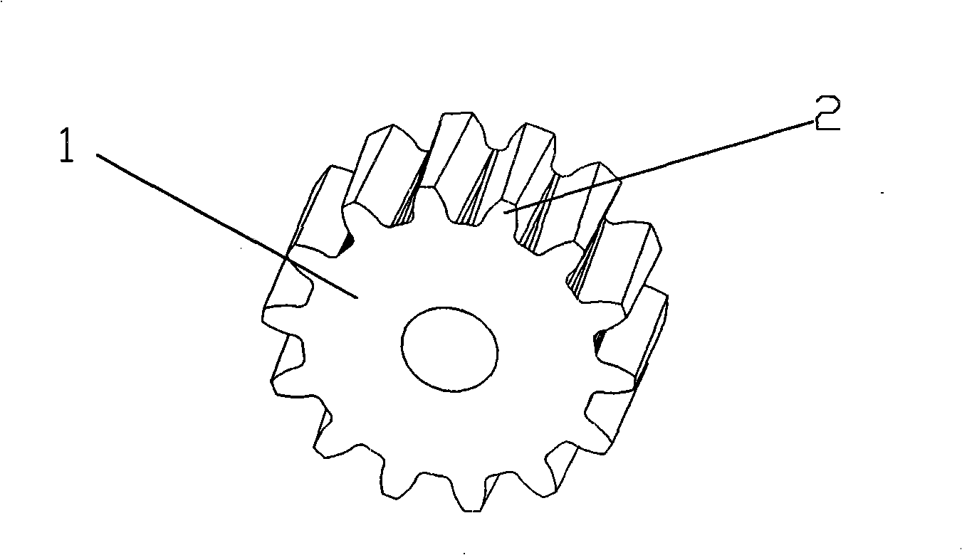
[0021] figure 1 It is a schematic diagram of the displacement gear structure of the present invention, as shown in the figure: the variable tooth thickness cylindrical displacement gear of this embodiment includes gear plate 1 and gear teeth 2, the gear adopts the form of tangential displacement, and the tangential displacement coefficient Along the axis of the gear plate 1, it changes linearly according to the law from small to large, and the tangential displacement coefficient of the two tooth surfaces of the gear tooth 2 is in the same direction from small to large, so that the two tooth surfaces of the gear teeth form a certain angle; Gear 2 also adopts the form of radial displacement, and the radial displacement coefficient is a constant value; during processing, radial displacement processing is first performed to the designed tooth thickness, and then tangential displacement processing is performed.

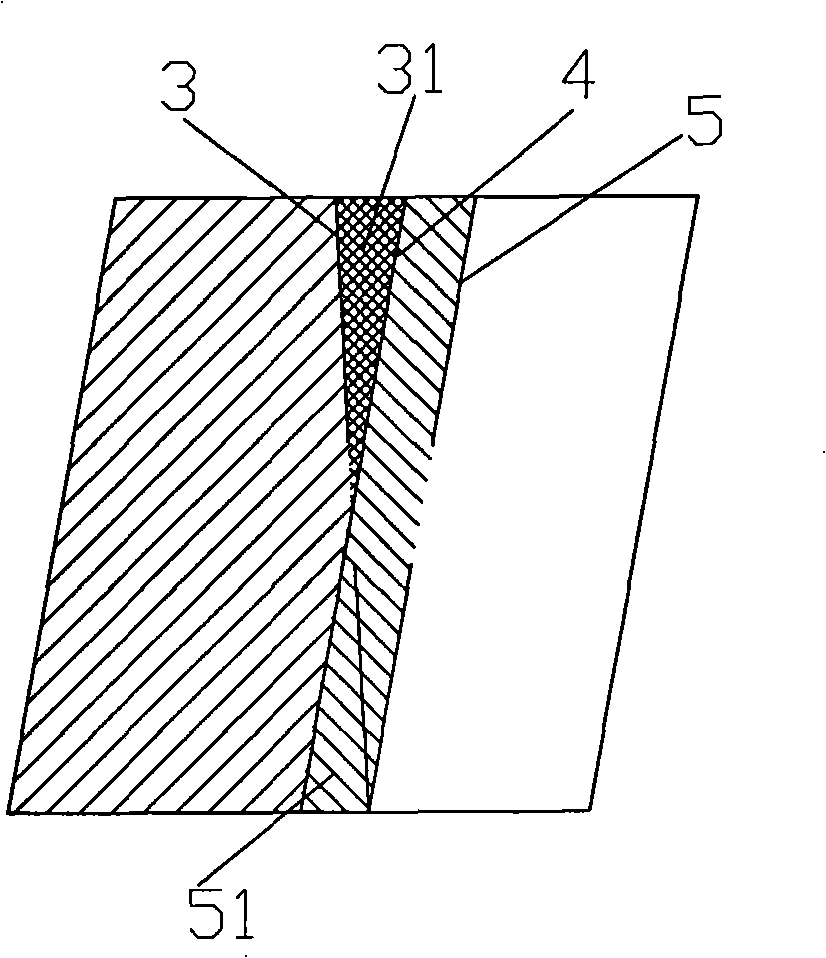
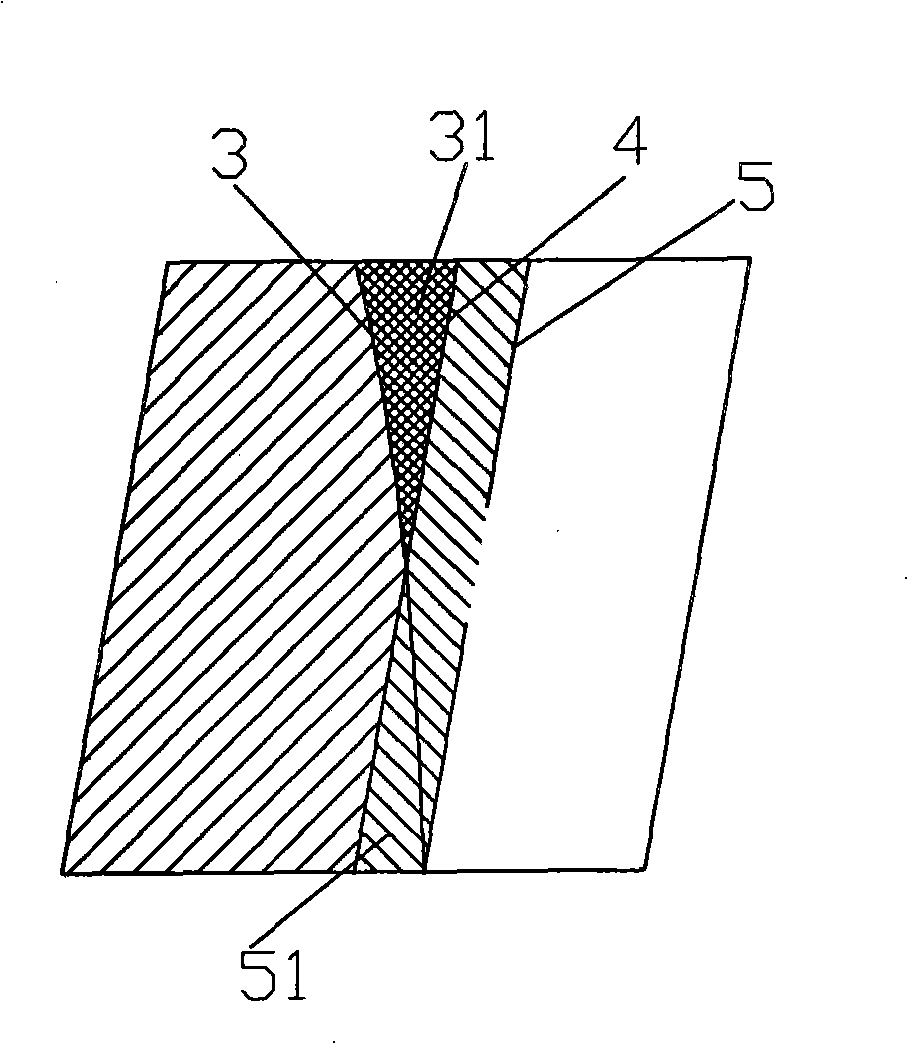
[0022] figure 2 It is the expansion diagram of the shifted gear alo...


PUM


Abstract

The invention discloses a variable tooth thickness profile shifted cylindrical gear and a transmission device using the same. The transmission device comprises a gear disk and a gear tooth; the gear adopts the tangential modification mode, and tangential modification coefficients change according to the order from small to big along the gear disk shaft, and becoming-bigger directions of tangential modification coefficients of two tooth faces of the gear tooth are the same; an included angle is formed between the two tooth faces of the gear tooth of the gear, and the meshing backlash can be adjusted by adjusting the axial relative position of gears meshed with each other, thereby effectively eliminating or reducing the backlash and return difference, reducing the vibration and noise and prolonging the service life; compared with the addendum modified variable thickness gear transmission used in the prior art, the transmission device of the invention has the advantages of smaller sliding ratio, good manufacturability of gear processing and low cost, etc.; compared with other clearance adjusting modes, the transmission device has the advantages of simple structure and small volume, etc.

Description

technical field [0001] The invention relates to a cylindrical displacement gear and a transmission device using the gear, in particular to a cylindrical displacement gear with variable tooth thickness and a transmission device using the gear. Background technique [0002] Gear transmission is used to transmit motion and power between two shafts. Compared with other mechanical transmissions, gears have the advantages of compact structure, stable operation, and low noise, so they are widely used in various machines and instruments. [0003] With the development of production technology and the demand for high-quality products, especially the development of precision heavy-duty transmission, higher requirements are put forward for the control of transmission accuracy and backlash. [0004] Existing technology In precision gear transmission, in order to achieve anti-backlash transmission or adjust meshing backlash, commonly used technical solutions include: eccentric bushing adj...

Claims


Application Information

Patent Timeline
IPC IPC(8): F16H55/17F16H55/18F16H55/08F16H1/06
Inventor 王光建陈小安
Owner CHONGQING UNIV
Learn More