
Low water temperature high-efficiency heat exchange tube full solution type evaporator

A flooded evaporator and heat exchange tube technology, which is applied in the field of evaporators, can solve the problems of difficulty in improving heat exchange efficiency, restricting the utilization of low-temperature water sources, and low ribbing coefficient of heat exchange tubes, so as to improve heat exchange efficiency and improve Heat exchange efficiency, uniform distribution effect

Inactive Publication Date: 2008-10-01
王全龄
View PDF0 Cites 11 Cited by
  • Summary
  • Abstract
  • Description
  • Claims
  • Application Information

AI Technical Summary

Problems solved by technology

The heat exchange tube generally uses a copper tube with spiral low fins (the height of the rib is about 1.5mm) rolled on the surface. Due to the low rib coefficient of the heat exchange tube, it is difficult to improve the heat exchange efficiency, so the heat exchange tube needs to be Adopt multi-water pass layout structure, and need to increase the flow rate, resulting in large volume and high cost of evaporator
And because the water temperature of many rivers, rivers, lakes, and seas in winter will be between 2 and -2.5°C, operating at this low water temperature, the current evaporator is extremely prone to freezing, thus limiting the water source heat pump's ability to protect the river and river in winter. Utilization of low-temperature water sources such as lakes, seas, etc.

Method used


Image

  • Low water temperature high-efficiency heat exchange tube full solution type evaporator
  • Low water temperature high-efficiency heat exchange tube full solution type evaporator
  • Low water temperature high-efficiency heat exchange tube full solution type evaporator

Examples


Embodiment Construction

[0016] The specific embodiment of the present invention will be described with reference to the accompanying drawings.

[0017] as attached figure 1 , the low water temperature high-efficiency heat exchange tube flooded evaporator includes an outer casing 5 configured with a water inlet 1, a water outlet 2, a refrigerant liquid inlet 3, and a gas outlet 4. The heat exchange tubes 7 are horizontally and fixedly assembled in the outer casing in the form of straight tubes and single water passes, and the outer casing is divided into a water inlet chamber and an outlet chamber connected through the heat exchange tube bundle, and a refrigerant liquid storage chamber placed between the two tube sheets. An oil return port 8 and a liquid level controller 9 are installed on the outer casing corresponding to the liquid level of the refrigerant in the storage chamber. A gas-liquid heat exchanger 11 composed of a tube-side cavity through which refrigerant liquid passes and a shell-side c...


PUM


Abstract

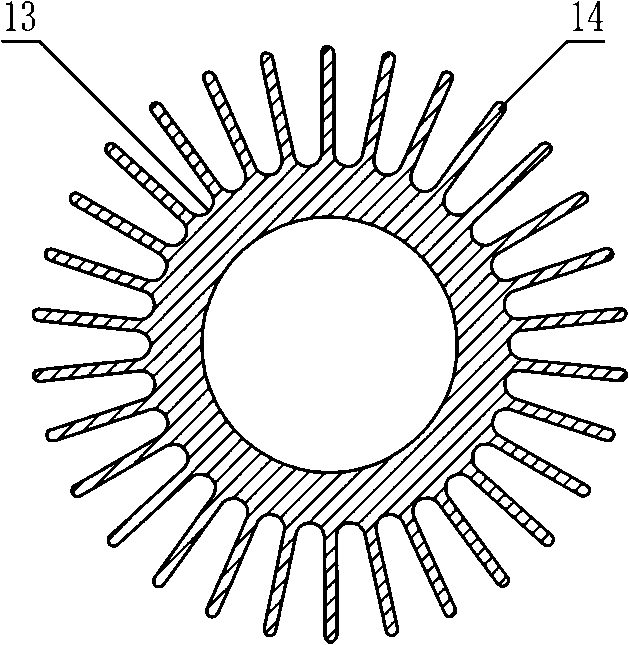
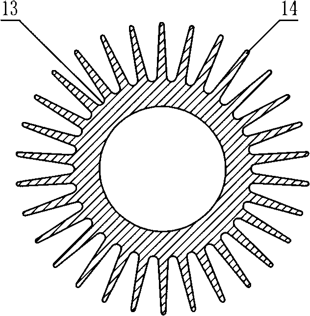
A low water temperature high-efficiency heat exchange tube flooded evaporator comprises a housing separated into water inlet and outlet chambers, and a refrigerant liquid storage chamber through a tube plate and the heat exchange tube; a return opening and a liquid level controller are installed corresponding to liquid level of the refrigerant; the heat exchange tube is composed of a parent tube integrated with axial rib which is in radiate uniform distribution along circumference at the outside surface of the parent tube and which has the height as 0.2 to 0.8 time of outside diameter of the parent tube; the housing of the heat exchange tube is allocated in straight tube single water path mode. The technical plan of the invention also comprises: a gas liquid heat exchanger arranged above the housing; an incoming liquid distributor arranged below the housing; and a water segregator arranged at the side of the water inlet chamber. The invention is provide with high rib coefficient heat exchange tube in straight single water path distribution, which enhances heat exchange efficiency of the evaporator greatly with reduced volume and reduced manufacturing cost, so as to meet requirement of water source heat bump using low temperature water from river, lake or sea as water source in winder.

Description

technical field [0001] The invention relates to an evaporator, in particular to a low water temperature high-efficiency heat exchange tube flooded evaporator. Background technique [0002] The water source heat pump has the characteristics of high efficiency and energy saving, and its operation requires a suitable available water source. Rivers, rivers, lakes, and seawater contain huge low-temperature heat energy. The effective use of this low-temperature heat energy will undoubtedly provide a wide range of application prospects for water-source heat pumps. Shell-and-tube flooded evaporators currently used to obtain heat energy from low-temperature water sources are mostly composed of a shell, tube sheets and heat exchange tubes placed in the shell. The tube side for low-temperature water to pass through and the shell side for refrigerant to pass through. , through the heat exchange tube for heat exchange. The heat exchange tube generally uses a copper tube with spiral low...

Claims


Application Information

Patent Timeline
Patent Type & Authority Applications(China)
IPC IPC(8): F28D15/02
Inventor 王全龄
Owner 王全龄
Learn More