Eureka AIR delivers breakthrough ideas for toughest innovation challenges, trusted by R&D personnel around the world.

Gas-liquid two-phase working substance coupled vibrations type thermo-acoustic engine

A thermoacoustic engine, coupled vibration technology, applied in the direction of machines/engines, mechanisms that generate mechanical power, mechanical equipment, etc. Low efficiency and other problems, to achieve flexible and convenient acoustic impedance characteristics, avoid sliding sealing problems, and improve the effect of sound power output capability

Inactive Publication Date: 2008-09-10
ZHEJIANG UNIV
View PDF1 Cites 12 Cited by
  • Summary
  • Abstract
  • Description
  • Claims
  • Application Information

AI Technical Summary

Problems solved by technology

In terms of using liquid as a thermoacoustic thermomechanical working medium, the research and development work mainly focuses on the theoretical and experimental studies of a thermoacoustic-driven magnetic fluid power generation system using liquid metal sodium as a working medium, but due to the small compressibility of liquid metal sodium and the excessive The large thermal conductivity makes the system need to operate under the high pressure condition of 10MPa-20MPa, the resonance frequency is high (the prototype with the axial length of the system is 1.22m, the working frequency is about 910Hz), the thermoelectric conversion efficiency is low, and the liquid metal sodium itself The danger is also worrying

Method used


Image

  • Gas-liquid two-phase working substance coupled vibrations type thermo-acoustic engine
  • Gas-liquid two-phase working substance coupled vibrations type thermo-acoustic engine
  • Gas-liquid two-phase working substance coupled vibrations type thermo-acoustic engine

Examples


Embodiment Construction

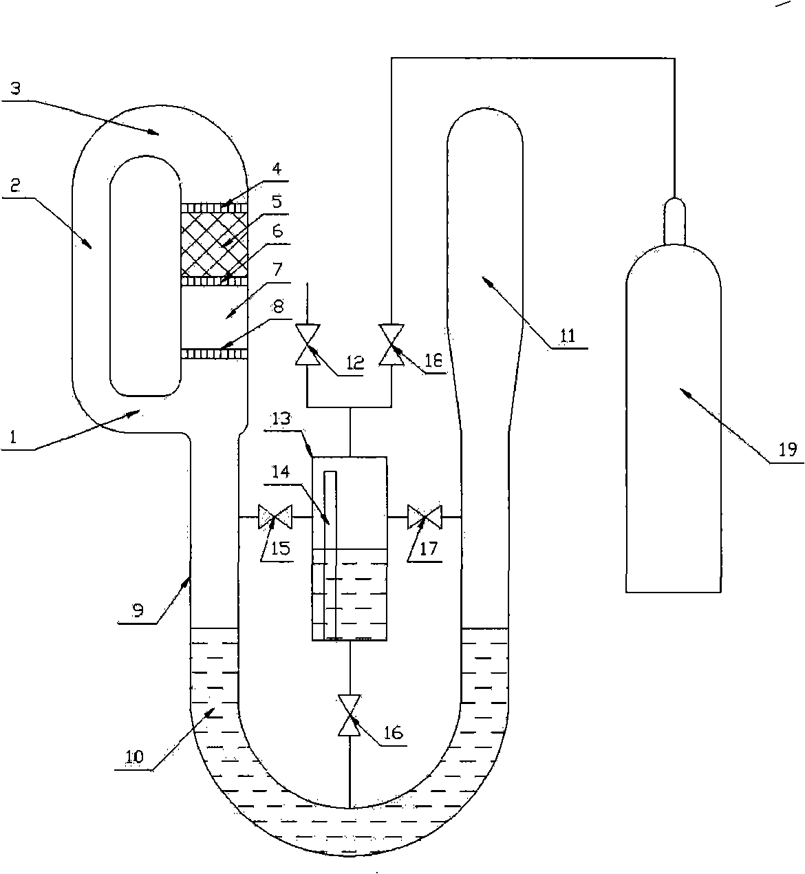
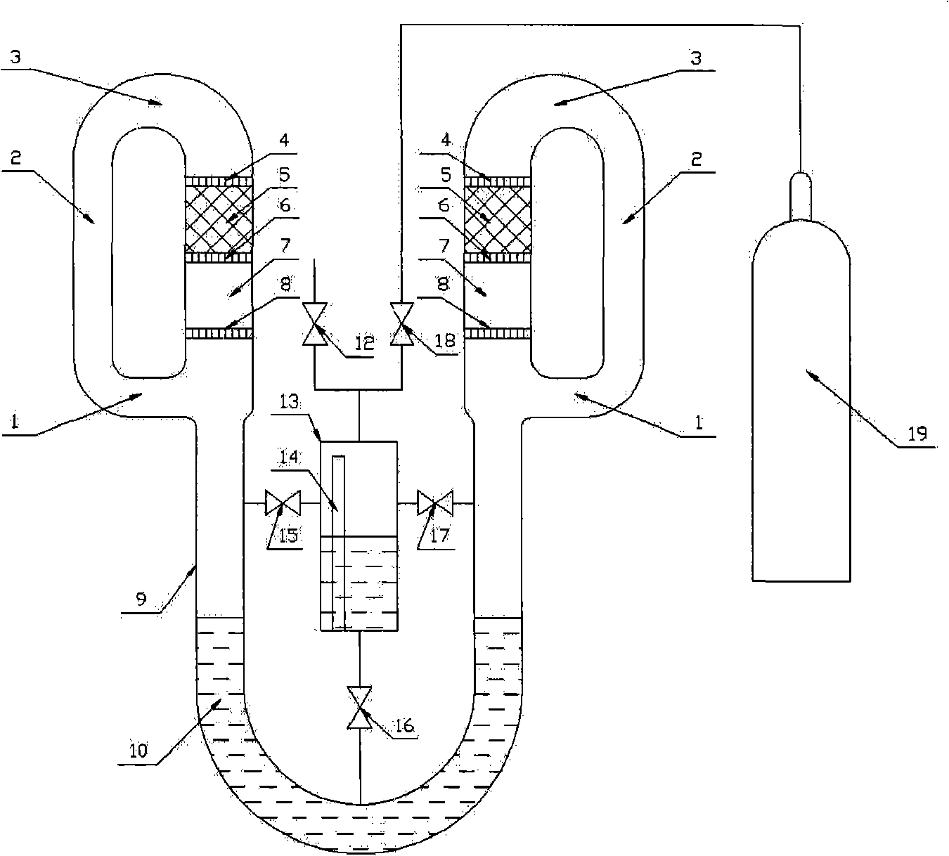
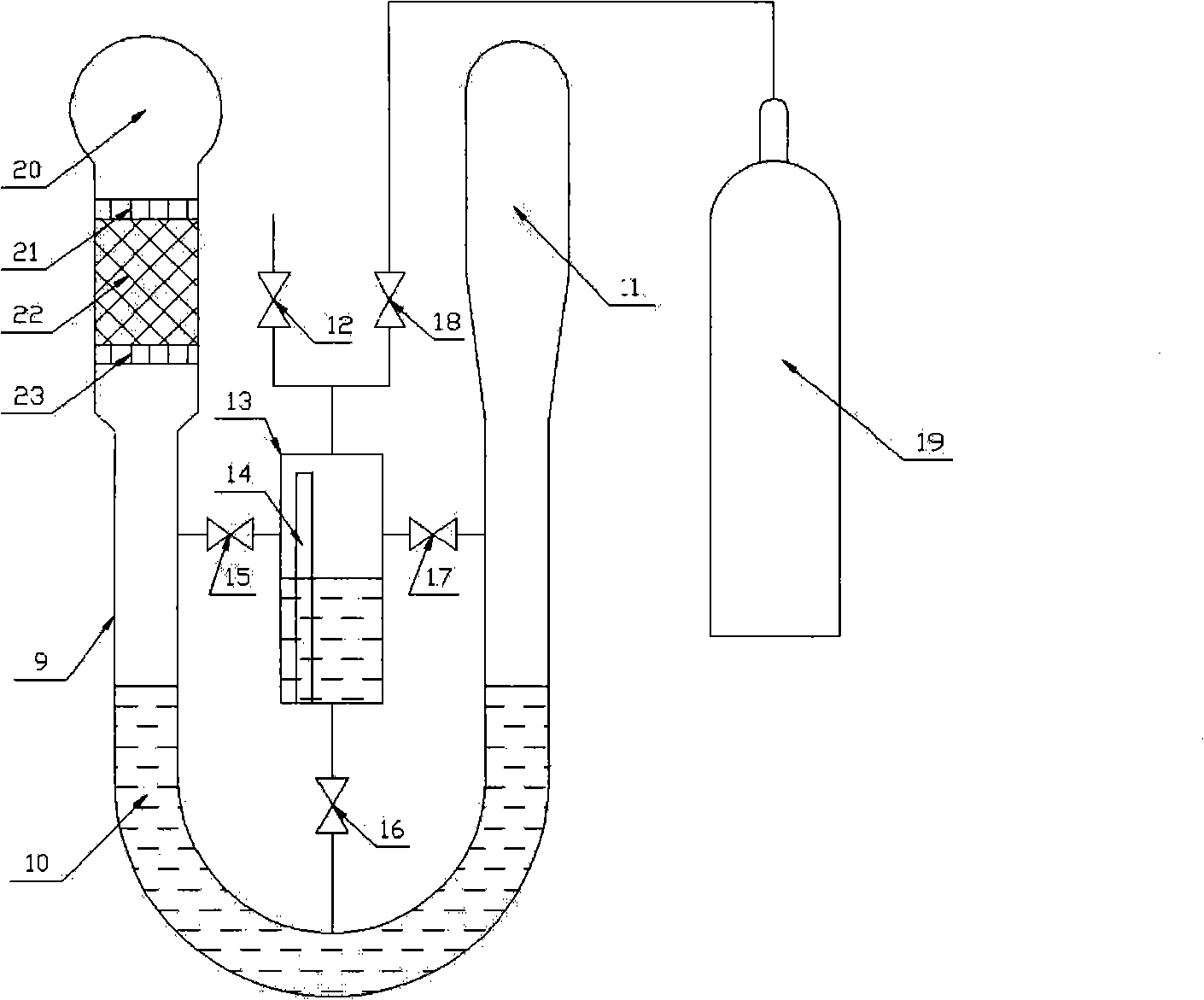
[0023] as attached figure 1 As shown, the gas-liquid two-phase working fluid coupling vibration thermoacoustic engine described in the present invention includes a loop traveling wave thermoacoustic core, a U-shaped resonant tube 9, a liquid piston 10, a resonant cavity 11 and an acoustic impedance connected in sequence. Regulator. The loop traveling wave thermoacoustic core includes a feedback tube 1, an acoustic sensing tube 2, an acoustic volume tube 3, a first water cooler 4, a regenerator 5, a heater 6, a thermal buffer tube 7 and a second water cooler connected in sequence 8. In the liquid piston 10, the room-temperature ionic liquid is placed in the U-shaped resonant tube 9 to form a liquid piston, thereby forming a gas-liquid coupling vibration together with the gas-phase working medium. The acoustic impedance regulator is characterized in that its main body is a gas-liquid balance tank 13, a liquid level gauge 14 is arranged inside it, and an exhaust valve 13 and an...


PUM


Abstract

The invention discloses a gas-liquid two-phase working substance coupled vibration type thermoacoustic engine, which comprises a loop traveling wave thermoacoustic core, a U-shaped resonant pipe, a liquid piston, a resonant cavity and an acoustic impedance regulator which are connected with each other in turn, wherein, the loop traveling wave thermoacoustic core comprises a feedback pipe, a phonoreceptive pipe, an acoustic capacitance pipe, a first water cooler, a heat regenerator, a heater, a thermal buffer tube and a second water cooler which are connected with each other in turn; and the liquid piston consists of a liquid column which is formed by arrangement of room-temperature ionic liquid inside the U-shaped resonant pipe; the acoustic impedance regulator comprises a gas-liquid surge tank, a fluid level gauge, an exhaust valve, an inflation valve, a steel cylinder, a first gas-phase balancing valve, a second gas-phase balancing valve and a liquid-phase balancing valve. The gas-liquid two-phase working substance coupled vibration type thermoacoustic engine introduces the room-temperature ionic liquid provided with 'zero' vapor pressure characteristic into the prior thermoacoustic engine to form a gas-liquid two-phase working substance coupled vibrating system, realizes acoustic oscillation and thermoacoustic conversion of the reinforced thermoacoustic engine through the acoustic impedance regulator, improves the acoustic power output capacity, and realizes operation below 10 hertz under the condition of relatively small physical dimension.

Description

technical field [0001] The invention relates to a thermoacoustic engine, in particular to a gas-liquid two-phase working fluid coupled vibration thermoacoustic engine. Background technique [0002] In recent years, a thermoacoustic heat engine consisting only of heat exchangers and pipe sections has been regarded as a new type of thermal system with no moving parts. Due to its advantages, it has attracted much attention from academia and industry, and has made breakthrough progress. In terms of thermoacoustic engines that only use gaseous working fluid, a traveling wave thermoacoustic Stirling engine with high efficiency and a large pressure ratio (1.4) has been successfully developed; a new standing wave-traveling wave cascade thermoacoustic engine has come out; Acoustic Stirling engine-driven traveling wave thermoacoustic refrigeration system in the room temperature zone obtained 250W and 435W cooling capacity at -22°C and 0°C respectively, and the COP was significantly i...

Claims


Application Information

Patent Timeline
IPC IPC(8): F03G7/00
Inventor 汤珂林小钢金滔陈国邦
Owner ZHEJIANG UNIV
Why Eureka
Eureka Blog
Learn More