
Sintering device flue gas multiple pollutant removing process and system thereof

A sintering machine and pollutant technology, which is applied in the directions of air quality improvement, electrostatic effect separation, dispersed particle filtration, etc., can solve the problems of unsatisfactory sintering flue gas purification treatment effect, low nitrogen oxide removal efficiency, and high equipment anti-corrosion requirements. , to achieve the effect of saving initial investment and operating costs of equipment, reducing flue gas flow resistance, and reducing engineering costs

Active Publication Date: 2008-09-03
WUHAN KAIDI ELECTRIC POWER ENVIRONMENTAL
View PDF5 Cites 58 Cited by
  • Summary
  • Abstract
  • Description
  • Claims
  • Application Information

AI Technical Summary

Problems solved by technology

However, the unit and the purification method will generate a large amount of wastewater, which not only requires reprocessing of the wastewater, but also requires extremely high anti-corrosion requirements for the equipment, resulting in complex processes and high operating costs.
At the same time, since the main component of nitrogen oxides in the flue gas is nitric oxide which is insoluble in water, and the technical solution of this invention mainly adopts a simple washing and absorption method, its removal efficiency for nitrogen oxides is too low
[0005] It can be seen that the effect of the existing technology on the purification and treatment of sintering flue gas is not ideal, especially the lack of research on the integrated treatment of sulfur dioxide, nitrogen oxides and dust particles in sintering flue gas

Method used


Image

  • Sintering device flue gas multiple pollutant removing process and system thereof

Examples


Embodiment Construction

[0027] Below for the discharged flue gas of a sintering machine, the present invention will be further described in detail in conjunction with the accompanying drawings:

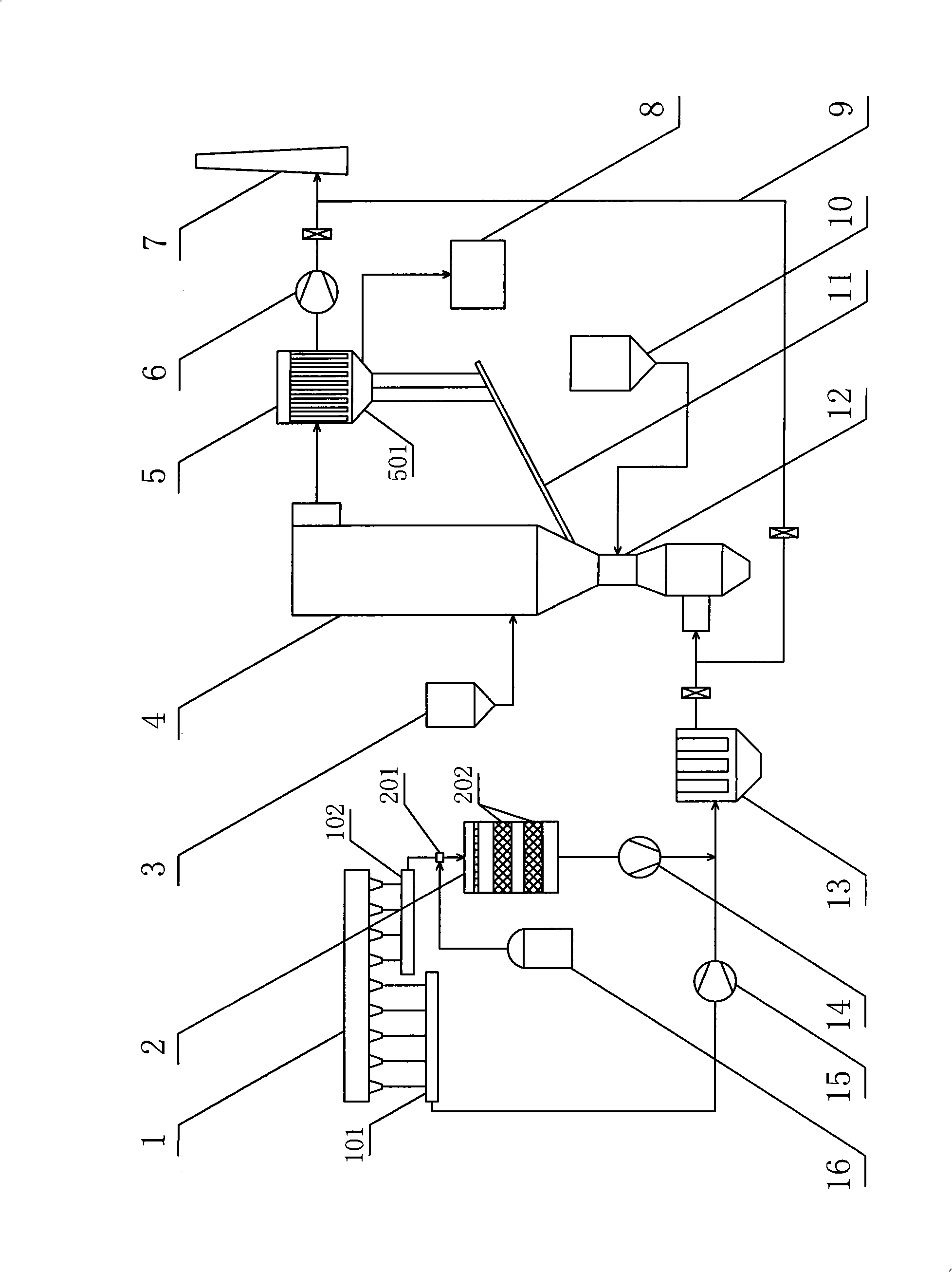
[0028] The sintering machine flue gas multi-pollutant removal system shown in the figure is mainly composed of a head flue gas header 101 and a tail flue gas header 102 for collecting flue gas at both ends of the sintering machine 1, and a flue gas header 102 for flue It is composed of SCR denitrification reactor 2, primary dust collector 13, circulating fluidized bed desulfurization reactor 4 and secondary dust collector 5 for removing various pollutants in the gas. The SCR denitrification reactor 2 includes an ammonia injection device 201 arranged outside the reactor and an SCR catalyst layer 202 arranged inside the reactor. The ammonia injection device 201 is connected to the ammonia storage tank 16, and the SCR catalyst layer 202 adopts a honeycomb or plate structure. The primary dust collector 13 adopts...


PUM


Abstract

The invention provides a process used for removing multiple contaminants in the off-gas of a sintering machine, as well as the system thereof. The process has the following steps: firstly, the machine tail off-gas undergoes SCR denitrification treatment; then, primary dedusting treatment is carried out to the denitrated machine tail off-gas and un-denitrated machine head off-gas at the same time, so as to remove the dust and ash particles in the off-gas; and then, circulating fluidized bed desulfurization treatment is carried out to the off-gas; finally, secondary dedusting treatment is carried out to the off-gas, so as to remove the resultant particles in the off-gas, the resultant particles are used for recycling, and the purified gas is separated out. The system thereof is mainly composed of a machine head off-gas header and a machine tail off-gas header which are used for collecting the machine head off-gas and the machine tail off-gas of the sintering machine, a SCR denitrification reactor which is used for removing the multiple contaminants in the off-gas, a primary dust remover, a circulating fluidized bed desulfurization reactor and a secondary dust remover. The process can carry out the classification integrated processing as well as the high efficient and synchronous removing to the sulfur dioxide, the nitrogen oxides and the dust in the sintering off-gas. The system has the characteristics of simple and compact whole design, low investment and running cost, and stable and reliable working.

Description

technical field [0001] The invention relates to a technology for purifying flue gas discharged from combustion, in particular to a process and system for removing multi-pollutants from flue gas of a sintering machine. Background technique [0002] The sintering machine is a commonly used equipment in the steel and metallurgical industries. The flue gas produced by it contains a variety of pollutants, such as dust, sulfur dioxide, nitrogen oxides, etc. The total area of ​​sintering machines in my country is 20000m2 2 Above, the emission of sulfur dioxide alone is more than 1 million tons, and sintering flue gas is one of the main sources of air pollutants in my country. [0003] At present, scientific and technical personnel have carried out some beneficial research on the technology and device for removing pollutants from sintering flue gas. For example, the Chinese Utility Model Patent Specification with the announcement number CN2920363Y introduces a "Large Sintering Mach...

Claims


Application Information

Patent Timeline
IPC IPC(8): B01D53/60B01D53/78B01D53/80B01D46/02B03C3/00
CPCY02A50/20
Inventor 韩旭朱敬李雄浩
Owner WUHAN KAIDI ELECTRIC POWER ENVIRONMENTAL
Learn More