
Display system and method for improving image display quality thereof

An image display and image technology, applied in static indicators, lighting devices, optics, etc., can solve the problems of animation quality degradation, backlight tube and image signal cannot be in the same phase, etc., to improve ghosting and animation quality , Improve the effect of dynamic quality

Inactive Publication Date: 2008-07-23
INNOLUX CORP
View PDF0 Cites 15 Cited by
  • Summary
  • Abstract
  • Description
  • Claims
  • Application Information

AI Technical Summary

Problems solved by technology

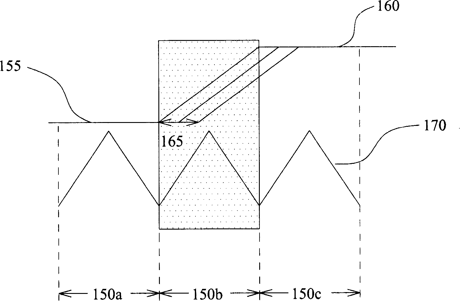
[0007] Therefore, the backlight tube and the image signal cannot be in the same phase, which will further lead to a decrease in the quality of the animation

Method used


Image

  • Display system and method for improving image display quality thereof
  • Display system and method for improving image display quality thereof
  • Display system and method for improving image display quality thereof

Examples


Embodiment 1

[0060] Please refer to FIG. 5a and FIG. 5b at the same time, which is a schematic diagram of a gain compensation waveform according to an application example 1 of the present invention. There are eight image areas in this application example, and the display period of each image area is 2ms. 300a and 300b are the out phase (Out Phase) of the control signal (triangular wave) of the backlight tube and the pixel gray scale change (gray scale rise or fall). waveform. 302a and 302b in FIG. 5a are product waveforms of the backlight tube waveform and the pixel gray scale. 304a and 304b are the fuzzy edge curves (Blur Edge Curve) of this pixel, wherein the blur edge time (BlurEdge Time; BET) is the response rise time (Rising Time) of the grayscale value from 10% to 90% and the response fall time ( Falling Time) changes from 90% to 10% of the total time. The blurred edge time is generally used to evaluate the animation quality. The smaller the blurred edge time, the shorter the afteri...

Embodiment 2

[0062] Considering another situation, reduce the number of image regions (that is, increase the display period of each image region; that is, the display period is 4 ms) to observe it. Please refer to FIG. 6a and FIG. 6b at the same time, which is a schematic diagram of a gain compensation waveform according to the second application example of the present invention. 320a, 320b, 322a, 322b, 324a, and 324b in FIG. 6a have not compensated the second gain coefficient (Gp) value of the present invention to the waveform of this application example, and its blurred edge time (BET) is 18.4ms. However, 326a, 326b, 328a, 328b, 330a and 330b in Fig. 6b are reduced to 13.8ms by the second gain coefficient (Gp) value compensation and Over Drive (Over Drive) method of the present invention. , so applying the system and method of the present invention can significantly shorten the fuzzy edge time (BET).

[0063] From the preferred embodiments of the present invention above, it can be seen ...


PUM


Abstract

The invention discloses a display system and a method thereof for promoting the image display quality. The system comprises a provided image control signal at least comprising a vertical synchronizing signal and a provided image area divided by at least one light source, wherein the image area comprises a plurality of pixels and each pixel receives one image signal for displaying image. A plurality of first gain coefficients are obtained by aid of the image control signal, wherein each first gain coefficient depends on the position relation of each pixel and each light source in the image area divided by each light source. And a dynamic compensation is carried out to obtain a compensation picture calculated by an operation of the image signal, received by each pixel, and each first gain coefficient in the image area divided by each light source. The different phase relationship of the control signal and pixel gray scale of backlight lighting tubes can be improved, and ghost images generated in dynamic images can be avoided by aid of measuring a plurality of the gain coefficients and engaging with the overload driving method, thereby improving animation quality.

Description

technical field [0001] The present invention relates to a system and method applied to a display, and in particular to a display system for making a backlight control signal and an image signal have the same phase and a method for improving image display quality. Background technique [0002] At present, TVs and monitors made of liquid crystal display technology are mass-produced, and have gradually replaced TVs and monitors made of traditional cathode ray tubes (Cathode Ray Tube; CRT). However, compared with cathode ray tubes, the current liquid crystal display technology still has deficiencies and limitations to be overcome and improved. [0003] The existing scanning backlight (Scan Backlight) technology is used to allow the liquid crystal display of the hold type (Hold Type) imaging method to effectively simulate the pulse type (Impulse type) imaging method of the cathode ray tube, and the liquid crystal display The internal backlight tube is turned on and off intermitt...

Claims


Application Information

Patent Timeline
Patent Type & Authority Applications(China)
IPC IPC(8): G09G3/34G09G3/36H05B37/02G02F1/13357G02F1/1335
Inventor 李嘉航杨富吉
Owner INNOLUX CORP
Learn More