Control apparatus and control method for passenger conveying machine
A technology for passenger conveyors and control devices, which is applied in transportation and packaging, energy efficiency of escalators, sustainable buildings, etc., can solve problems such as large impacts, complex devices and prices, and achieve the effects of reducing impacts and preventing noise and vibration
- Summary
- Abstract
- Description
- Claims
- Application Information
AI Technical Summary
Problems solved by technology
Method used
Image
Examples
no. 1 Embodiment approach
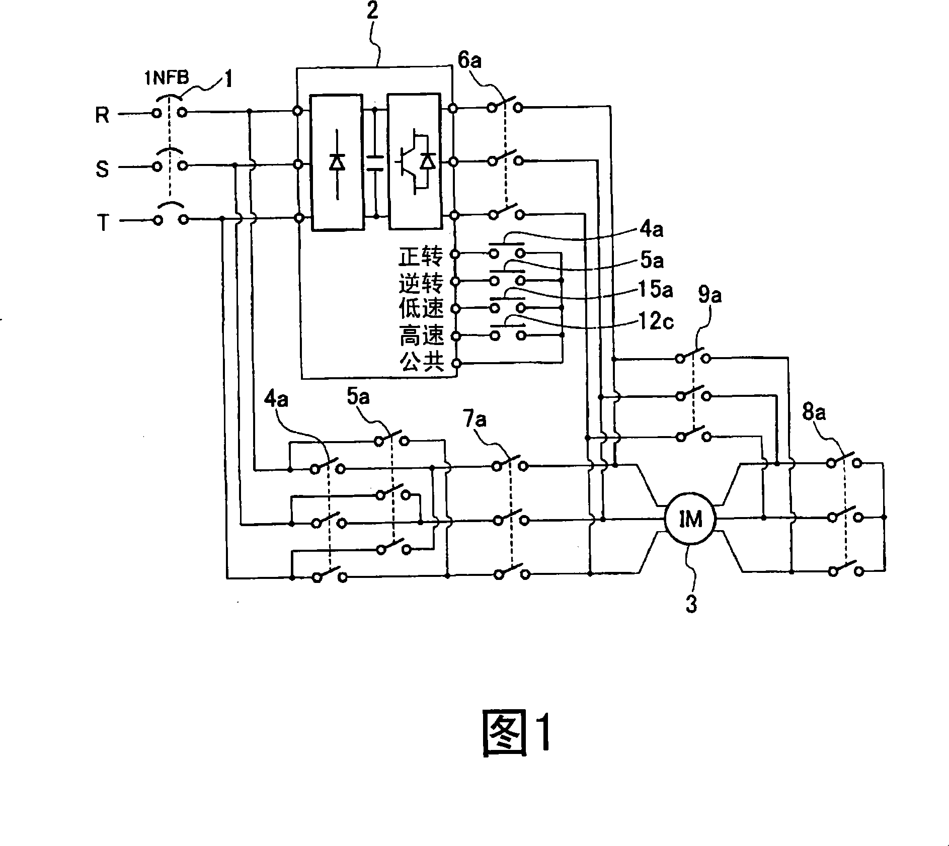
[0022] First, a first embodiment of the present invention will be described with reference to FIGS. 1 and 2 . In addition, FIG. 1 is a main circuit diagram of the control device of this embodiment, and FIG. 2 is a control circuit diagram of the control device.
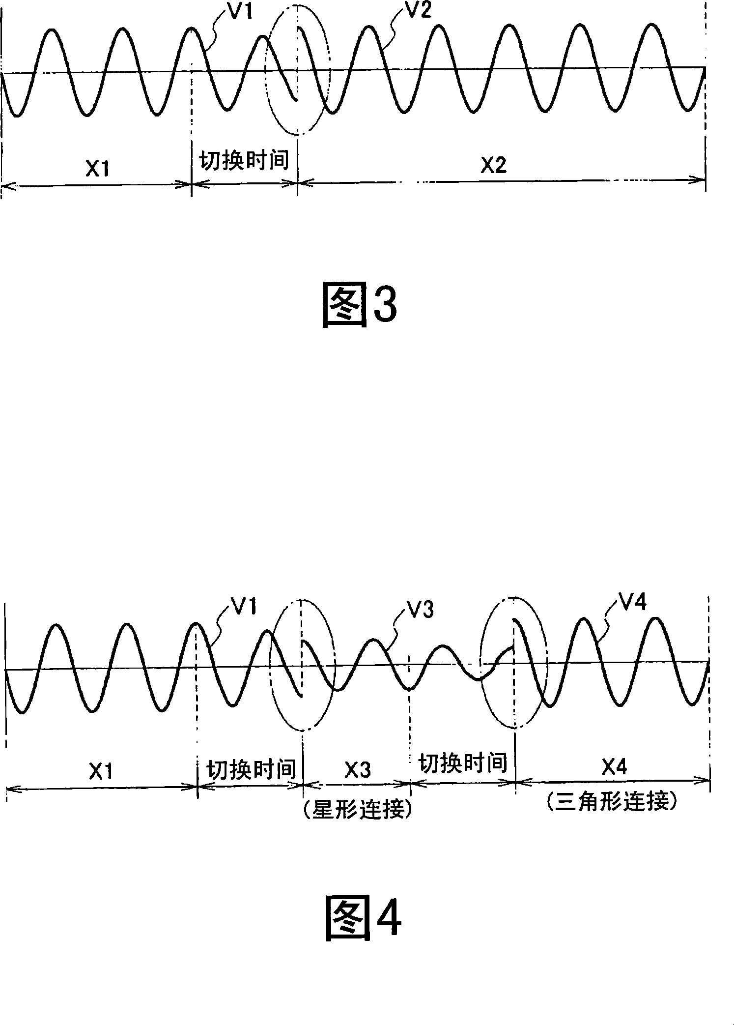
[0023] As shown in FIG. 1, the control device of this embodiment is configured to include a conversion device 2 that converts three-phase AC from commercial power sources R, S, and T into a three-phase AC with variable voltage and variable frequency, and can selectively The three-phase alternating current from the commercial power sources R, S, T and the three-phase alternating current converted by the conversion device 2 are switched in an orderly manner to supply the induction motor 3 for moving the steps of the passenger conveyor. Furthermore, a structure is adopted in which the connection of the three-phase power supply lines of the induction motor 3 can be selectively switched between the star connection and the d...
no. 2 Embodiment approach
[0042] Next, a second embodiment of the present invention will be described with reference to FIGS. 5 and 6 . In addition, FIG. 5 is a main circuit diagram of the control device according to this embodiment, and FIG. 6 is a control circuit diagram of the control device.
[0043] As shown in FIG. 5 , the control device of this embodiment is configured to include a conversion device 2 that converts three-phase AC from commercial power sources R, S, and T into a three-phase AC with variable voltage and variable frequency, and can selectively The three-phase alternating current from the commercial power sources R, S, T and the three-phase alternating current converted by the conversion device 2 are switched in an orderly manner and supplied to the induction motor 3 for moving the steps of the passenger conveyor. In addition, the three-phase power lines of the induction motor 3 each have a starting resistor 27 connected in series, and a circuit that passes through the starting resi...
no. 3 Embodiment approach
[0062] Next, a third embodiment of the present invention will be described with reference to FIG. 8 . In addition, FIG. 8 is a main circuit diagram of the control device of this embodiment. The control circuit diagram of the control device of this embodiment is the same as the circuit diagram of the second embodiment shown in FIG. 6 , and this circuit diagram is used.
[0063] As shown in FIG. 8 , the control device of the present embodiment has a configuration in which a starting choke coil 28 is provided instead of the starting resistor 27 , and the other configurations are the same as those of the control device of the second embodiment. That is, in the control device of the present embodiment, when the power supply of the induction motor 3 is switched, the three-phase power supply lines of the induction motor 3 are temporarily provided with the choke coils 28 for starting respectively by using the control circuit shown in FIG. 6 to lower the power supply voltage. After th...
PUM
 Abstract
Description
Claims
Application Information
 - R&D
- Intellectual Property
- Life Sciences
- Materials
- Tech Scout
- Unparalleled Data Quality
- Higher Quality Content
- 60% Fewer Hallucinations
Browse by: Latest US Patents, China's latest patents, Technical Efficacy Thesaurus, Application Domain, Technology Topic, Popular Technical Reports.
© 2025 PatSnap. All rights reserved.Legal|Privacy policy|Modern Slavery Act Transparency Statement|Sitemap|About US| Contact US: help@patsnap.com


