Dynamic control type electronic equipment dissipating heat method and system

A technology of electronic equipment and heat dissipation method, which is applied in the field of dynamic control electronic equipment heat dissipation method and system, can solve the problems of internal circuit burning of blade servers, excessive time and energy, and inconsistency with human resource application cost and economic benefits.

Inactive Publication Date: 2008-06-18
INVENTEC CORP
View PDF0 Cites 5 Cited by
  • Summary
  • Abstract
  • Description
  • Claims
  • Application Information

AI Technical Summary

Problems solved by technology

However, in practical applications, a disadvantage of this static correspondence fan speed control method is that circuit design engineers need to spend more time and energy to calculate the required temperature-to-speed correspondence table, so it is...

Method used


Image

  • Dynamic control type electronic equipment dissipating heat method and system
  • Dynamic control type electronic equipment dissipating heat method and system
  • Dynamic control type electronic equipment dissipating heat method and system

Examples


Embodiment Construction

[0023] The following describes in detail the embodiments of the dynamic control electronic equipment heat dissipation method and system of the present invention in conjunction with the accompanying drawings.

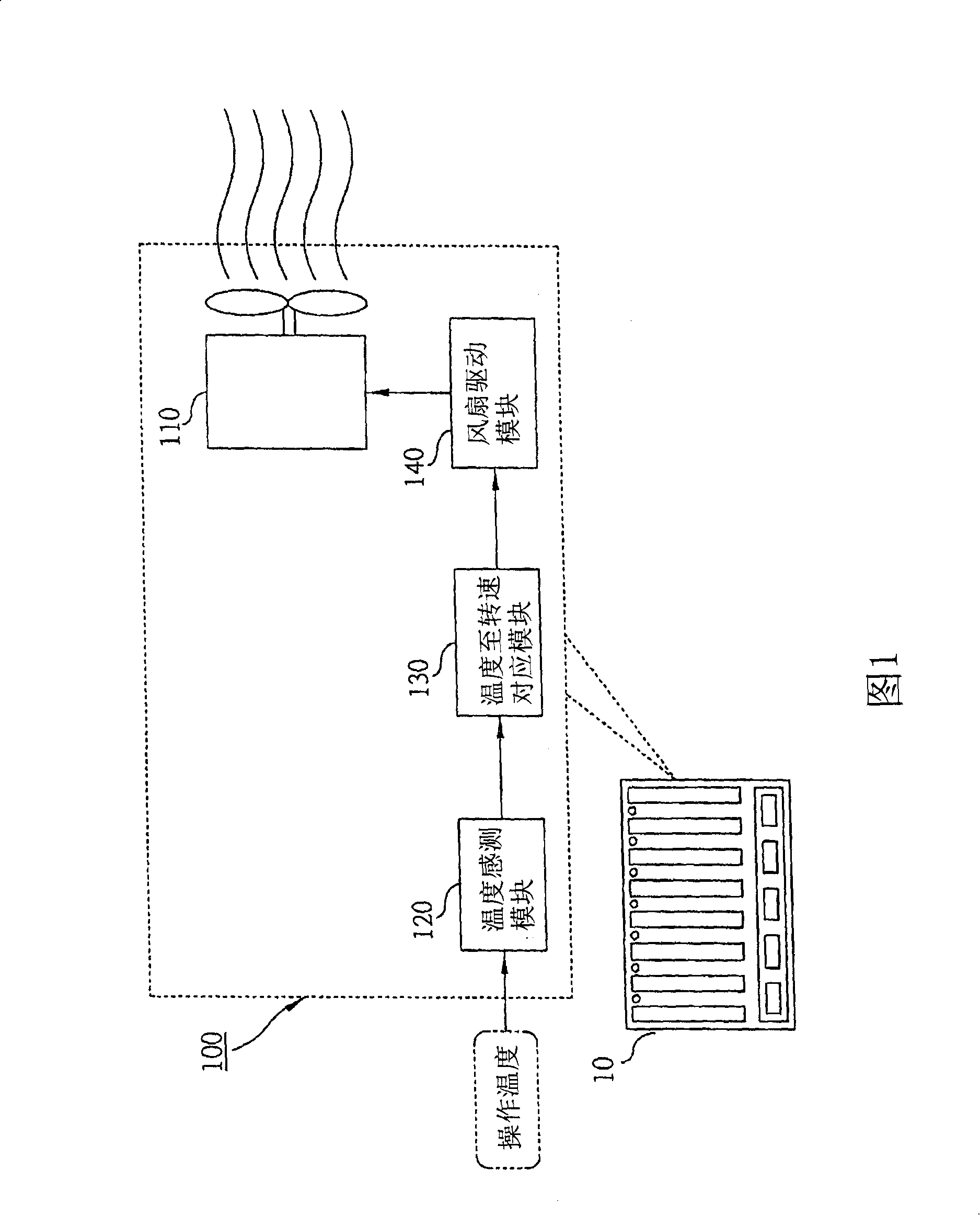
[0024] FIG. 1 shows the application method and internal structure of the dynamically controlled electronic equipment heat dissipation system of the present invention (such as the part enclosed by the dotted box indicated by the reference number 100 ). As shown in the figure, the dynamic control cooling system 100 for electronic equipment of the present invention is mounted on an electronic equipment 10 in practical applications, such as a blade server, desktop personal computer, or notebook computer (the blade server is used as an example below for illustration) , to provide a dynamically controlled cooling function for the blade server 10 .

[0025] As shown in FIG. 1, the internal basic structure of the dynamic control type electronic equipment cooling system 100 of th...


PUM


Abstract

A dynamic controlling type heat dissipating method and system of electronic equipment can be used for being matched with a piece of electronic equipment such as a blade server, a desktop personal computer or a laptop to provide a dynamic controlling type heat dissipating function. The invention is characterized in that the operating temperature range of the electronic equipment is divided into two stages: a linear stage and a high temperature stage. When in the linear stage, a linear way is used for corresponding to a fan speed value; on the contrary, when in the high temperature stage, a dynamic controlling way is used for controlling the fan rotational speed to reduce the temperature to the linear stage rapidly.

Description

technical field [0001] The invention relates to a heat dissipation technology for electronic equipment, in particular to a dynamic control type heat dissipation method and system for electronic equipment. Background technique [0002] Electronic devices often generate heat due to power consumption during operation. If the heat is not removed, the circuit elements or chips in the electronic equipment may be burned and cause a destructive shutdown. A general solution to this problem is to install a cooling device, such as a fan device, in the body frame of the electronic device, so as to remove the heat generated by the electronic device during operation. For example, one or more fan devices are usually arranged in the body frame of a blade server or a desktop personal computer to use wind force to blow off the heat generated during operation, thereby protecting its internal host circuit from Burned due to excessive temperature. [0003] In practice, the activation of the f...

Claims


Application Information

Patent Timeline
IPC IPC(8): H05K7/20H01L23/34G06F1/20G05D23/00
CPCH01L2924/0002
Inventor 王宗斌
Owner INVENTEC CORP
Why Eureka
Try Eureka