
Drill

A technology of drill bit and main body, which is applied in the field of drill bit for drilling processing, which can solve the problems of inability to perform high precision, vibration, cutting edge breakage, etc., and achieve the effect of preventing the reduction of strength/rigidity, ensuring rigidity, and preventing breakage

Inactive Publication Date: 2008-06-11
MITSUBISHI MATERIALS CORP
View PDF3 Cites 2 Cited by
  • Summary
  • Abstract
  • Description
  • Claims
  • Application Information

AI Technical Summary

Problems solved by technology

[0009] However, in the drill described in Patent Document 3, the position of the supply hole on the cross section perpendicular to the axis is not particularly limited, and some of the supply holes are provided near the chip discharge flute or near the axis of the drill body. In this case, even if the openings of two or more supply holes are formed on one cutting edge to form a rib-shaped reinforcement, the rigidity of the drill body is significantly reduced, vibration occurs during drilling, and high-precision machining cannot be performed. The possibility of breaking the drill body or cutting edge due to cutting resistance

Method used


Image

  • Drill
  • Drill
  • Drill

Examples


Embodiment Construction

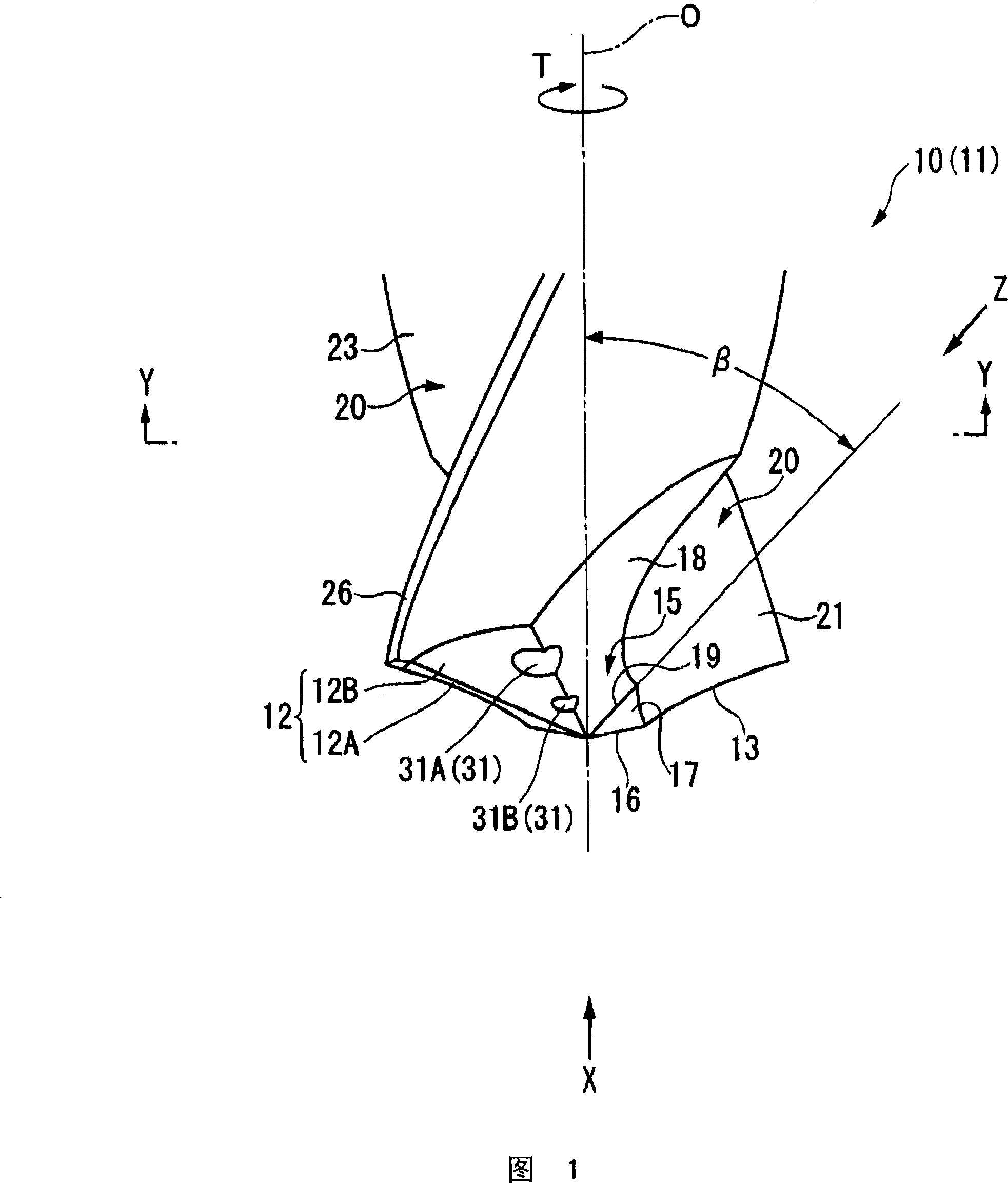
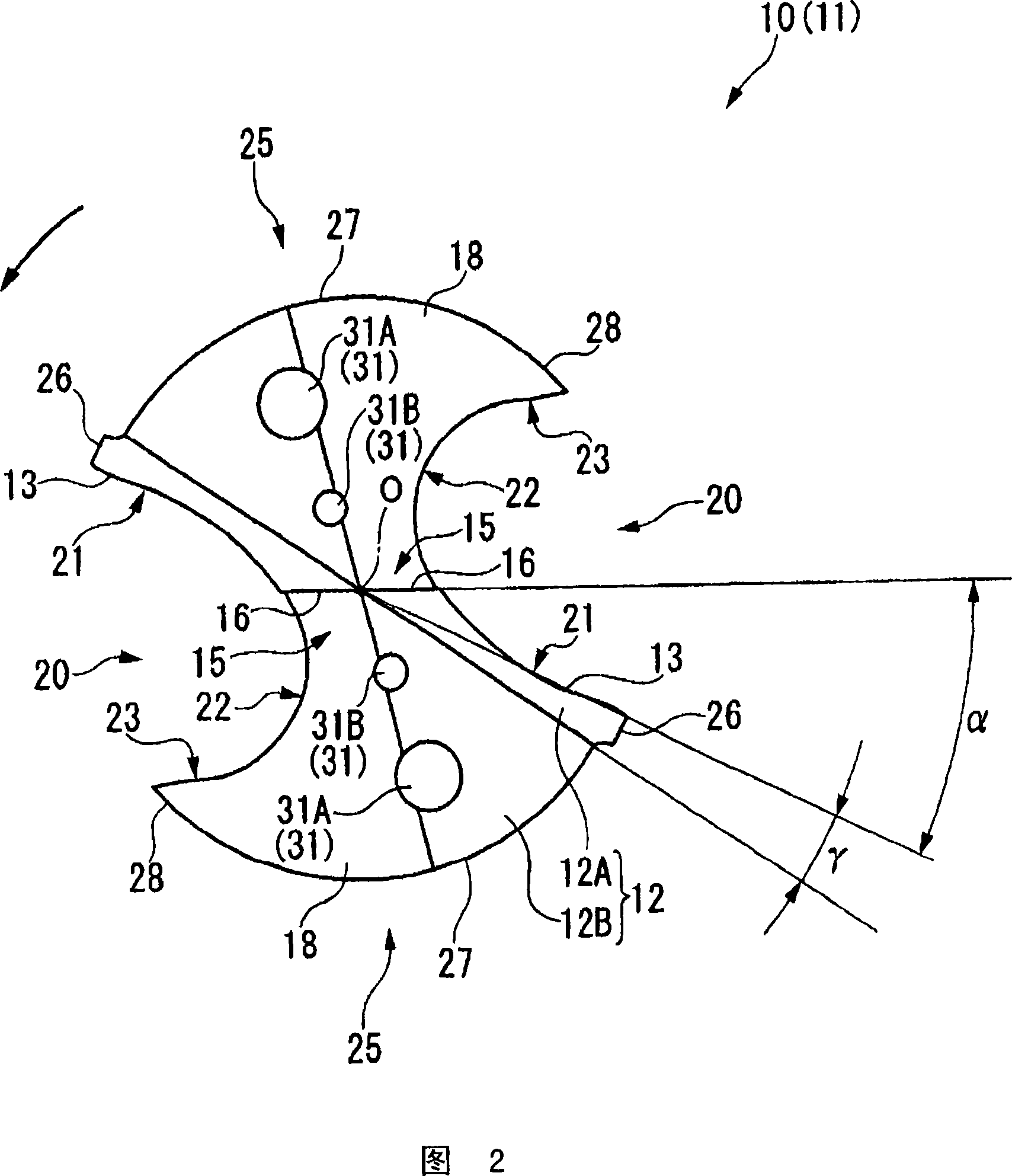
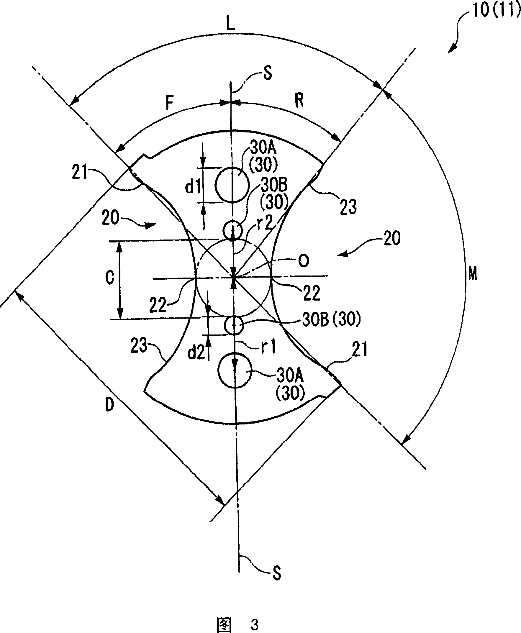
[0034] A drill which is an embodiment of the present invention will be described with reference to the drawings. A drill according to an embodiment of the present invention is shown from FIG. 1 to FIG. 3 .

[0035] The drill according to this embodiment is used when drilling a workpiece made of aluminum. The drill body 10 of this drill is made of a hard material such as cemented carbide, and as shown in FIG. The shank is gripped by a spindle of a machine tool or the like, and the tip side (lower side in FIG. 1 ) of the drill body 10 is used as the cutting edge portion 11 .

[0036] On the outer periphery of the cutting edge portion 11, a pair of chip discharge flutes 20, 20 are twisted toward the rear side in the drill rotation direction T at a constant twist angle from the tip relief surface 12 to the rear end side in the axis O direction. O is formed with 180° rotational symmetry. The chip discharge groove 20 has a wall surface 21 facing forward in the drill rotation dire...


PUM


Abstract

A plurality of cutting oil feed holes extend from the proximal side towards the distal side are provided in a drill body located on a reference line that extends towards a circumferential central portion of an outer circumferential surface of the drill body split by a chip discharge groove from an axis in a cross section orthogonal to the axis. A cutting oil feed hole that is located on the radial outermost side is used as a first cutting oil feed hole, and a cutting oil feed hole that is on the radial innermost side is used as a second cutting oil feed hole. Two or more openings of the cutting oil feed holes are provided in one cutting edge as the plurality of cutting oil feed holes are formed in the vicinity of the intersection ridgeline portion between the distal flank face and the second thinned face.

Description

technical field [0001] The present invention relates to a drill for drilling a hole in a material to be cut, and in particular to a drill suitable for forming a hole in a material to be cut made of a ductile material such as aluminum. Background technique [0002] Conventionally, as the above-mentioned drill, there is known a so-called double-edged drill in which a cutting edge portion is formed on the front end side of a drill body rotating around an axis, and a pair of chips extending toward the rear end side are formed on the outer periphery of the cutting edge portion. The discharge flute forms a cutting edge at the intersection ridgeline between the wall surface of the chip discharge flute facing forward in the drill rotation direction and the tip relief surface of the cutting edge portion. [0003] In general, on the drill body of such a double-edged drill, as shown in Patent Documents 1 and 2, for example, a pair of supply holes for cutting oil are drilled from the re...

Claims


Application Information

Patent Timeline
Patent Type & Authority Applications(China)
IPC IPC(8): B23B51/00B23B51/06
CPCB23B51/06Y10T408/455Y10T408/9097B23B51/00B23B51/02
Inventor 柳田一也马渕雅行东裕之
Owner MITSUBISHI MATERIALS CORP
Learn More