
Random working angle precision electrolytic machining method and machine tool

An electrolytic machining machine tool, working angle technology, applied in electrochemical machining equipment, metal machining mechanical parts, metal machining equipment, etc., to achieve the effect of good operating space, small size and light weight

Inactive Publication Date: 2008-05-28
NANJING UNIV OF AERONAUTICS & ASTRONAUTICS
View PDF0 Cites 20 Cited by
  • Summary
  • Abstract
  • Description
  • Claims
  • Application Information

AI Technical Summary

Problems solved by technology

[0004] The purpose of the present invention is to provide a precision electrolytic machining method and machine tool at any working angle to solve the problem of timely discharge of gas and other electrolytic products generated during the electrolytic machining of tiny holes

Method used


Image

  • Random working angle precision electrolytic machining method and machine tool
  • Random working angle precision electrolytic machining method and machine tool
  • Random working angle precision electrolytic machining method and machine tool

Examples


Embodiment Construction

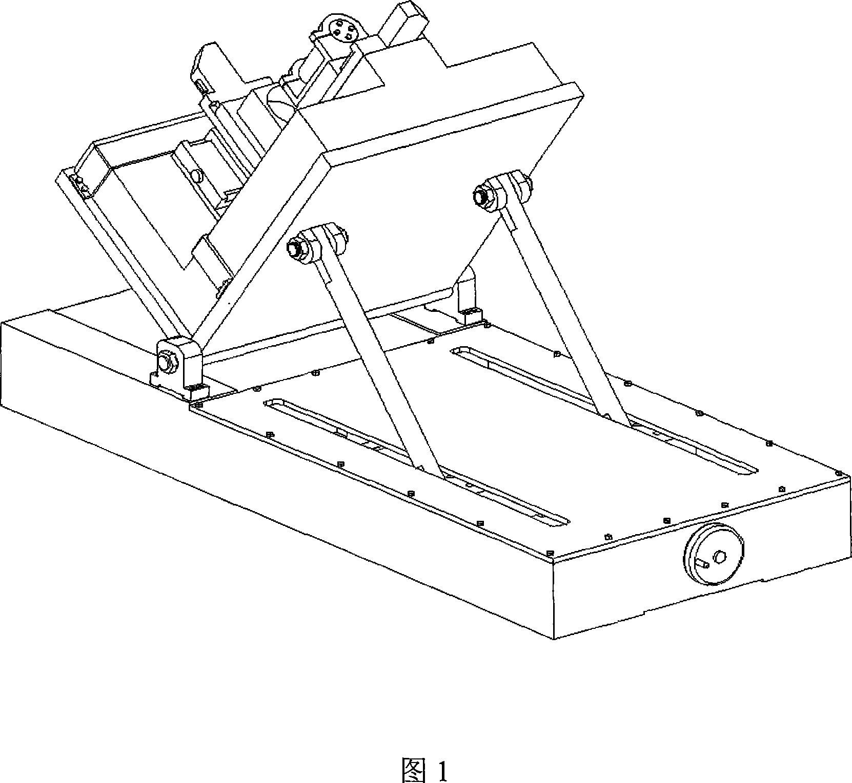
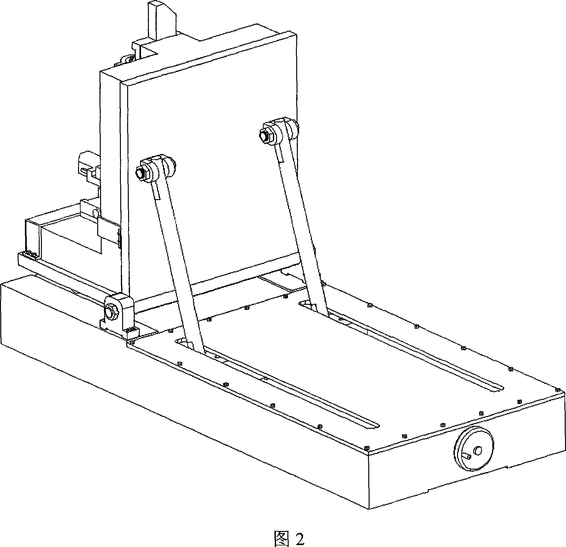
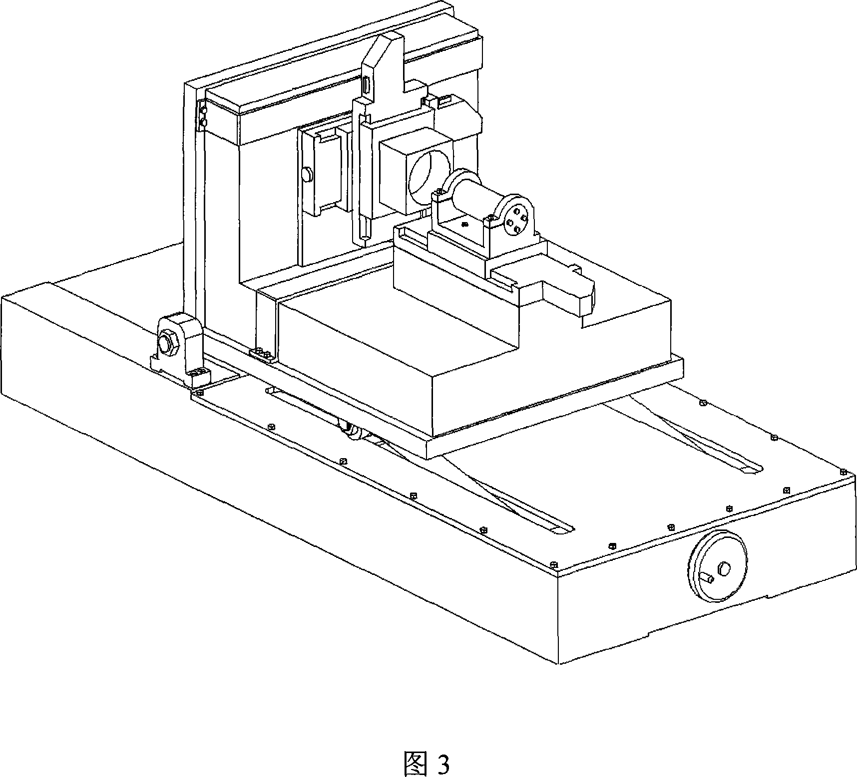
[0019] The present invention—arbitrary angle adjustable precision electrolytic machining machine tool, as shown in Figure 6, includes x workbench 1, y workbench 2, work box 3, spindle and its lead-in device 13, z workbench 5, bed 6 , Angle adjustment device 7. The high-speed spindle is installed on the z workbench, and the axis is perpendicular to the x and y workbenches; the working box is installed on the y workbench, and the y workbench is installed on the x workbench. During the machining process, the tool electrode installed on the high-speed spindle is perpendicular to the workpiece; the bed is installed on the angle adjustment device.

[0020] When using different processing techniques, choose different machine tool layouts, vertical, horizontal or a suitable processing posture between vertical and horizontal, to ensure the timely update of the electrolyte and the timely removal of electrolytic products.

[0021] Because the tool electrode is installed on the high-spee...


PUM


Abstract

The invention relates to an arbitrary work-angle accurate ECM method and a machine tool, belonging to the technical field of ECM machining. The method makes use of an angle-regulating device to lead the main shaft of the machine tool to realize a vertical style, a horizontal style or any angle between the vertical and horizontal styles machining positions and to synthetically solve the draining of ECM outcome and the venting of gases generated in the ECM process. The machine tool comprises a machine tool base, a machine tool body (6), a work table which consists of an X work table (1), a Y work table (2) and a Z work table (5) and is arranged on the machine tool body (6), a work box (3) and a main shaft (13) provided with an electricity conducting device. The invention is characterized in that an angle regulating device (7) is arranged between the machine tool body (6) and the machine tool base. The design of the invention is modularized and miniaturized and foreign work tables are adopted. The whole machine tool has light weight and small volume and can carry out an angle regulation and an ECM for a three-dimensional microstructure with excellent operation space.

Description

technical field [0001] The invention belongs to the field of micro-electrolytic machining machine tools, and in particular relates to a precision electrolytic machining method with any working angle and a machine tool. Background technique [0002] More and more precision and ultra-precision metal microstructures appear in the fields of aerospace, instrumentation, and precision mold manufacturing. Electrolytic machining technology has also been widely studied and applied to precision micromachining and precision micromanufacturing. [0003] At present, the micro electrolytic machining machine tool basically does not rotate the main shaft or the main shaft rotates at a low speed, which cannot fully update and replenish the electrolyte in the machining gap during micro hole machining. According to the layout of the spindle, the existing micro-electrolytic machining machine tools only have two cases: vertical spindle and horizontal spindle, and it is impossible to realize verti...

Claims


Application Information

Patent Timeline
IPC IPC(8): B23H3/00B23Q1/25
Inventor 朱荻黄绍服刘壮曾永彬
Owner NANJING UNIV OF AERONAUTICS & ASTRONAUTICS
Learn More