Exhaust gas cleaner
An exhaust purification device and electrode technology, which is applied in the direction of exhaust devices, noise reduction devices, chemical instruments and methods, etc., can solve the problems of voltage waveform and current waveform deviation, non-implemented control collection, large power consumption, etc., and achieve reactance change Reduce, achieve energy utilization, and reduce the effect of digesting power
- Summary
- Abstract
- Description
- Claims
- Application Information
AI Technical Summary
Problems solved by technology
Method used
Image

Examples
Embodiment 1
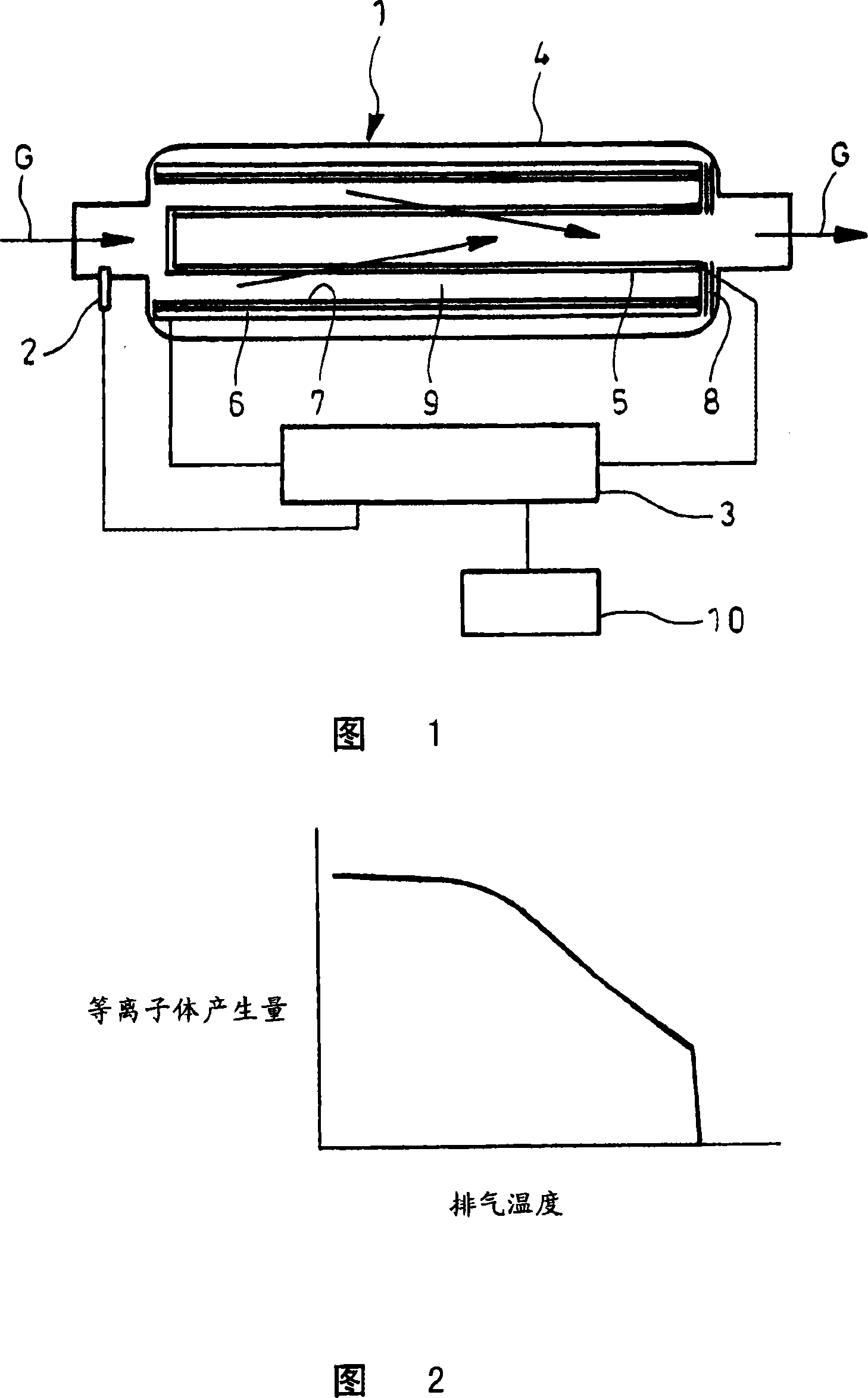
[0079] 1 and 2 show the first embodiment of the exhaust gas purification device of the present invention. This exhaust gas purification device is equipped with a collection chamber 1, a temperature sensor 2, and a discharge control unit 3.
[0080] The collection chamber 1 is equipped with: a housing 4 assembled in the flow path of the exhaust gas G to be purified; a hollow inner electrode 5 formed by a conductive filter that can collect particulates, and in the housing 4 A cylindrical outer electrode 6 is arranged inside the housing 4 so as to surround the inner electrode 5 in the circumferential direction; a dielectric body 7, such as ceramic, which covers the outer electrode 6 The inner surface.
[0081] Furthermore, in the flow path of the exhaust gas G, a particulate filter to which cordierite or the like is applied is installed separately from the collection chamber 1.
[0082] As the above-mentioned conductive filter, there is a form in which fibrous metals are laminated an...
Embodiment 2
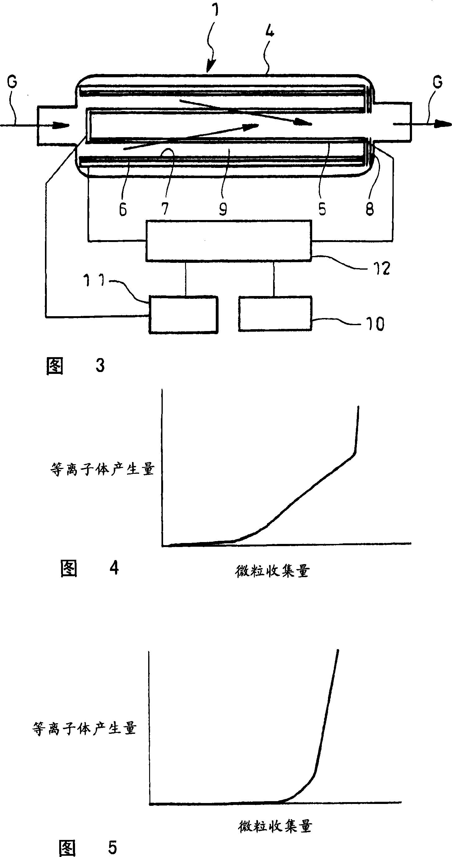
[0097] Figures 3 to 5 show a second embodiment of the exhaust purification device of the present invention. This exhaust purification device is equipped with a collection chamber 1, a collection amount estimation mechanism 11, and a discharge control unit 12, a collection chamber 1, an on-board power supply 10 It has the same structure as shown in FIG. 1.
[0098] The collected amount estimation mechanism 11 measures the internal pressure of the housing 4, the electrical characteristics of the inner electrode 5 (voltage value, current value, and impedance value when energized) and other parameters, based on the collected amount of particles of the inner electrode 5 obtained through actual measurement in advance and Based on the correlation of the measured values of the parameters, the amount of particles collected by the inner electrode 5 at that time is calculated.
[0099] An on-vehicle power supply 10 and a collection amount estimation mechanism 11 are connected to the discha...
Embodiment 3
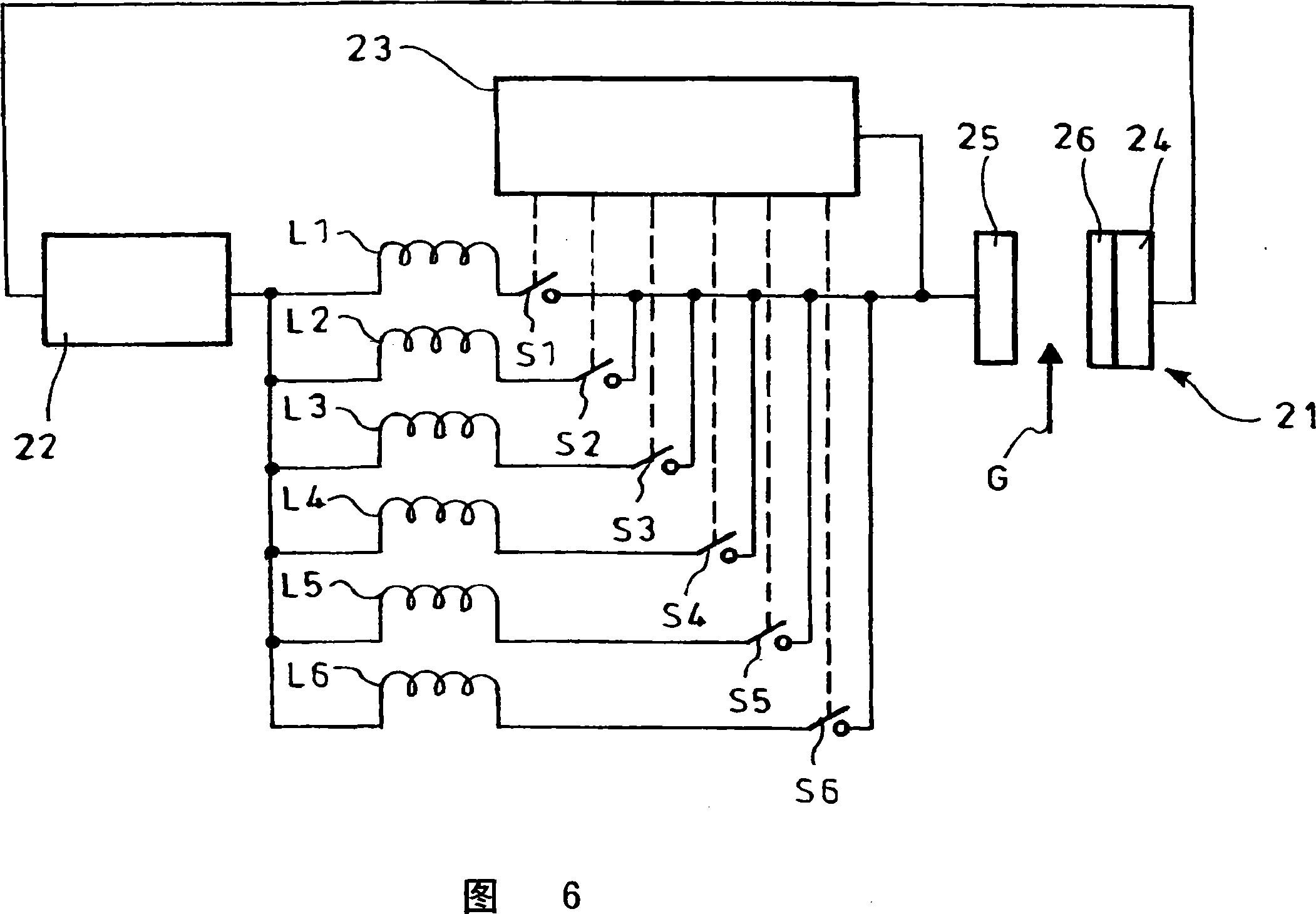
[0111] Fig. 6 shows a third embodiment of the exhaust gas purification device of the present invention. This exhaust gas purification device is equipped with a collection chamber 21, a high-voltage output mechanism 22 that outputs alternating current for discharge, a plurality of inductors L1 to L6, and an inductance Control mechanism 23.
[0112] The collection chamber 21 is equipped with a pair of electrodes 24 and 25, which are arranged in the flow path of the exhaust gas G which is the object of purification; The filter constitutes the other electrode 25.
[0113] The shape of these electrodes 24 and 25 may be any of a cylindrical shape, a flat plate facing type, or a lattice type.
[0114] As the above-mentioned conductive filter, there is a form in which fibrous metals are laminated and sintered to be integrated, a form in which a sintered body of metal powder and a fine metal mesh are laminated and sintered, or by Sintering is a form in which metal powder is placed on a fine ...
PUM
 Abstract
Description
Claims
Application Information
 - Generate Ideas
- Intellectual Property
- Life Sciences
- Materials
- Tech Scout
- Unparalleled Data Quality
- Higher Quality Content
- 60% Fewer Hallucinations
Browse by: Latest US Patents, China's latest patents, Technical Efficacy Thesaurus, Application Domain, Technology Topic, Popular Technical Reports.
© 2025 PatSnap. All rights reserved.Legal|Privacy policy|Modern Slavery Act Transparency Statement|Sitemap|About US| Contact US: help@patsnap.com