
Watt-hour meter reading method, system and user terminal

A meter reading method and technology for a meter reading system, applied in electrical signal transmission systems, transmission systems, signal transmission systems, etc., can solve the problems of high cost and difficulty in power supply departments, improve stability, facilitate control and management, and be practical strong effect

Inactive Publication Date: 2008-04-30
CHENGDU YANXINGGUO TECH CO LTD
View PDF1 Cites 19 Cited by
  • Summary
  • Abstract
  • Description
  • Claims
  • Application Information

AI Technical Summary

Problems solved by technology

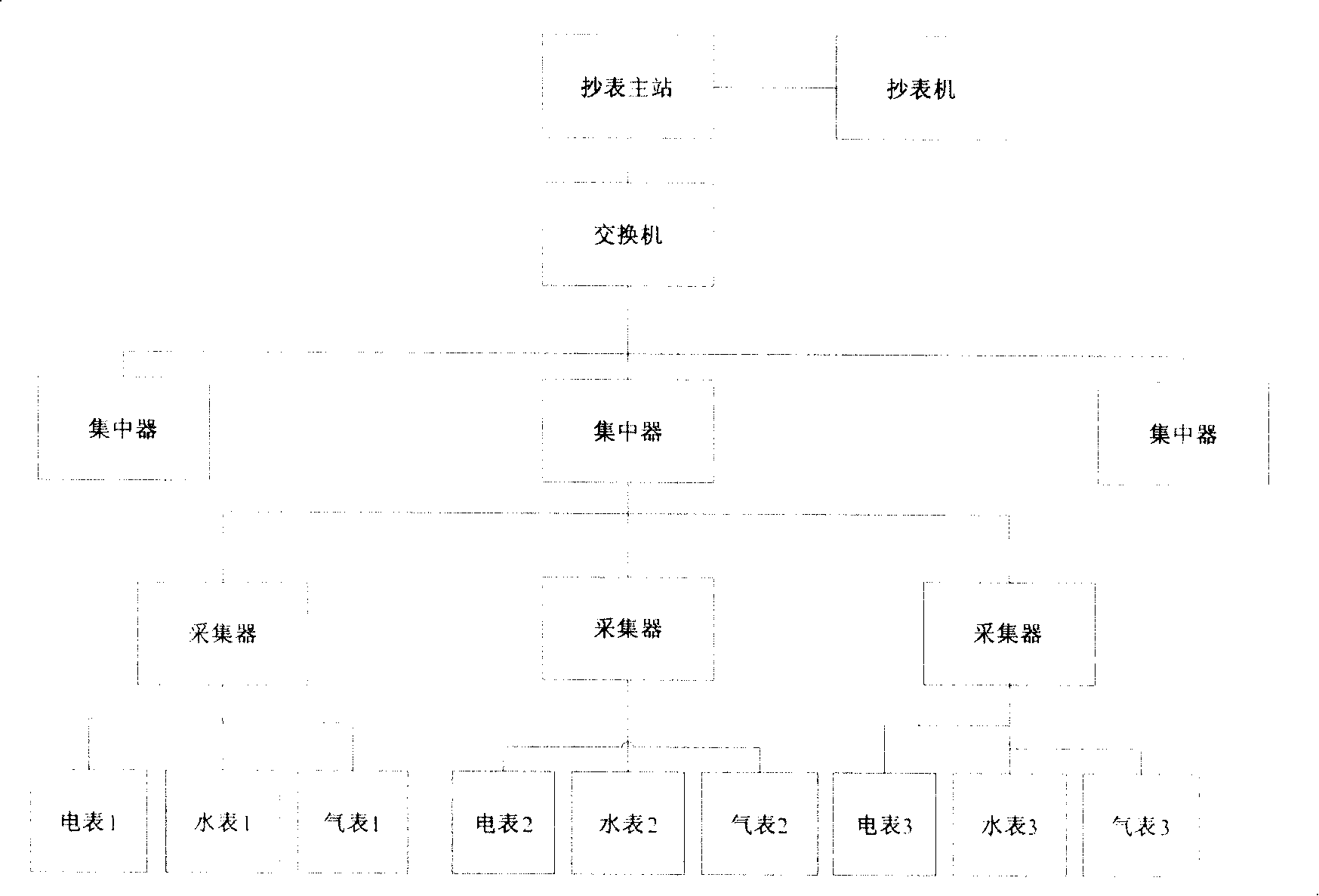
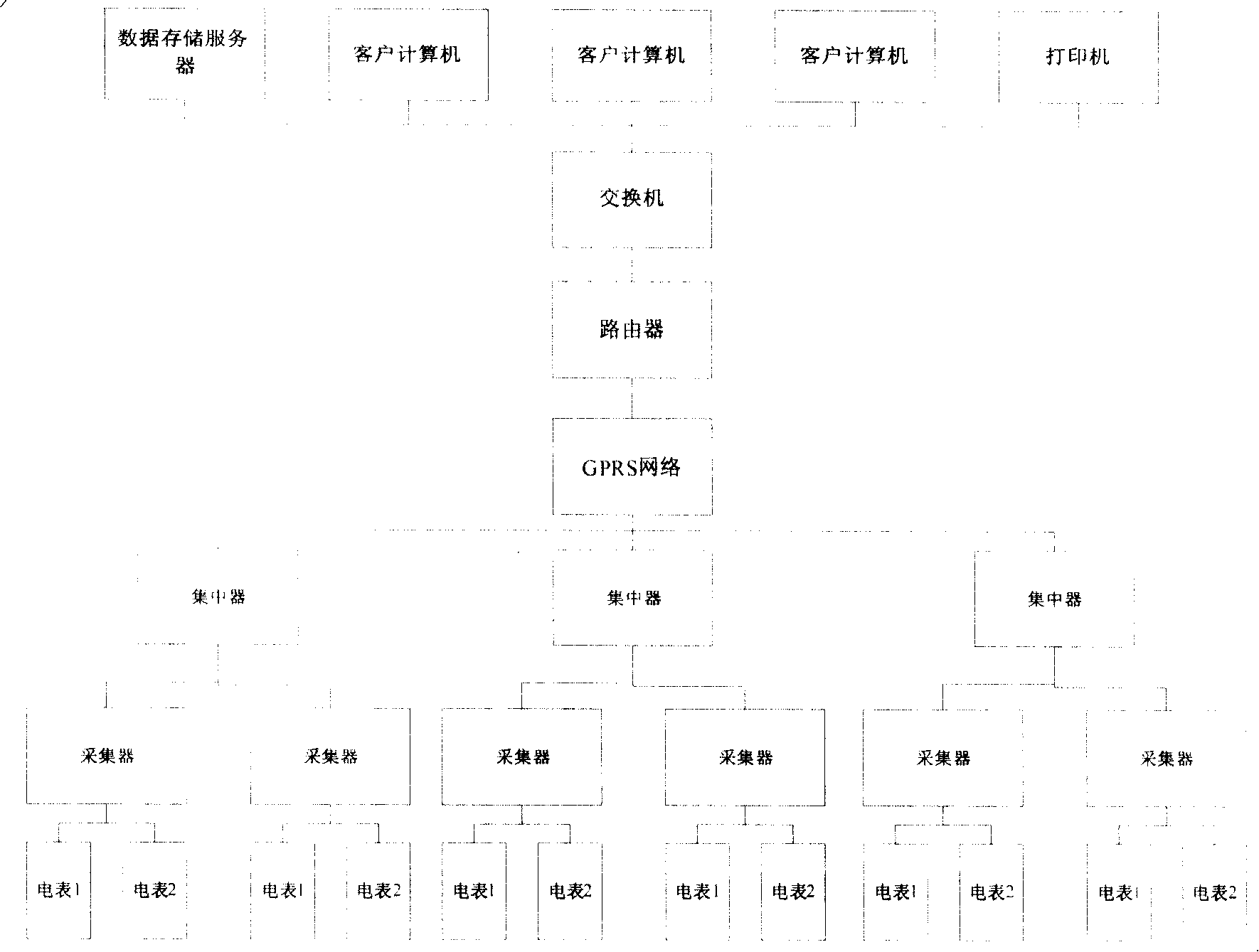
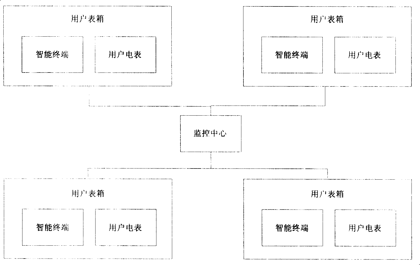
exist image 3 In the system shown, with figure 1 The difference between the systems shown is that image 3 In the system shown, the concentrator and the collector are combined into one, which also results in high cost, which is unbearable for the power supply department; and has high requirements for the electric energy meter itself

Method used


Image

  • Watt-hour meter reading method, system and user terminal
  • Watt-hour meter reading method, system and user terminal
  • Watt-hour meter reading method, system and user terminal

Examples


Embodiment 1

[0095] The invention provides a meter reading system for electric energy meters, such as Figure 4 As shown, the system includes a plurality of user terminals 401, a central station 402 and a server 403; wherein,

[0096] The user terminal 401 is placed on the side of the corresponding electric energy meter and configured with an address, collects and stores the electricity consumption data of the electric energy meter; judges the instruction transmitted by the central station 402, and sets the user terminal according to the judgment result , or send the energy meter data stored by the user terminal to the central station 402; the central station 402 is connected to the user terminal 401 through the network, and communicates with the server 403 through the network or the near-end interface; wherein, Receive the energy meter data sent by the user terminal 401, process it and send it to the server 403; receive the instruction sent by the server 403, process it and send it to all...

Embodiment 2

[0157] The present invention also provides a meter reading method for an electric energy meter, which includes steps: step 1, the user terminal collects and stores the electricity consumption data of the electric energy meter according to preset parameters; the preset parameters here include the user terminal Clock, power consumption attribute and type of the managed energy meter, recording gear, recording accuracy, time-sharing period, power-off and power-off, etc. are set for parameter setting.

[0158] Step 2, the server sends an instruction to the central station; Step 3, after the central station receives the instruction, it processes the instruction and sends it to all user terminals; wherein, the user terminal is configured with an address; step 4 After the user terminal receives the instruction, it judges the instruction, and transmits the stored electric energy meter data to the server according to the judgment result or performs corresponding settings on the user term...


PUM


Abstract

The invention provides an electric energy meter reading method and a system and a user terminal. The method comprises collecting power consumption data by a user terminal according to pre-set parameters and storing the data; sending an instruction by a server to a center station; and receiving the instruction, processing the instruction by the center station and transmitting the instruction to all user terminals; wherein the user terminal is allocated with an address; and the user terminal discriminates the instruction when receiving the instruction and transmits the electric energy meter data stored therein to the server according to the discrimination result, or the user terminal of the electric energy meter is set correspondingly. The invention can achieve non-online meter reading and obviate various error codes caused by online monitoring mode, thereby improving the operation stability of the system. The user terminal can be directly connected with the prior electric energy meter without changing the electric energy meter thereby to significantly reduce the system cost.

Description

technical field [0001] The present invention relates to the field of electric energy supply and management, in particular to the management and analysis of user electricity consumption information and the payment of fees, and specifically relates to a method for reading electric energy meters for collecting, managing and analyzing electricity consumption information of users , system and user terminals. Background technique [0002] In the prior art, the user's electric energy meter can be read manually, but the disadvantage of this method is that the management and cost accounting workload is large and the work efficiency is low, so the charging cycle is long and the charging and meter reading cannot be synchronized. There are statistical errors. [0003] At present, in order to overcome the disadvantages brought by the traditional manual meter reading method, a meter reading system using the existing communication system for automatic meter reading has emerged. [0004] ...

Claims


Application Information

Patent Timeline
Patent Type & Authority Applications(China)
IPC IPC(8): G08C19/00H04L29/00
Inventor 卢泳
Owner CHENGDU YANXINGGUO TECH CO LTD
Learn More