Plastering composite wall with reinforcing steel bar and/or metal net equipped at inter and outer or two-side

A technology of composite wall and building main body, applied in the field of building composite wall, can solve the problems of high cost, incomplete connection structure, troublesome construction, etc., and achieve the effect of reducing the degree of damage, reducing the horizontal earthquake action, and high safety.

Inactive Publication Date: 2011-12-14
吴淑环
View PDF1 Cites 0 Cited by
  • Summary
  • Abstract
  • Description
  • Claims
  • Application Information

AI Technical Summary

Problems solved by technology

[0005] The purpose of the present invention is to provide a composite wall with steel bars and / or metal mesh plastering on the inside and outside or on both sides. The connection structure of the bundled composite thermal insulation wall with support is not comprehensive, and it is not suitable for some heat insulation requirements. High areas may have problems of troublesome construction and high cost. Therefore, the composite wall with multiple connection structures is proposed, which is more convenient for construction, greatly reduces the cost of composite walls, and more widely satisfies different areas, different buildings, and different structures. Requirements

Method used


Image

  • Plastering composite wall with reinforcing steel bar and/or metal net equipped at inter and outer or two-side
  • Plastering composite wall with reinforcing steel bar and/or metal net equipped at inter and outer or two-side
  • Plastering composite wall with reinforcing steel bar and/or metal net equipped at inter and outer or two-side

Examples


specific Embodiment approach 1

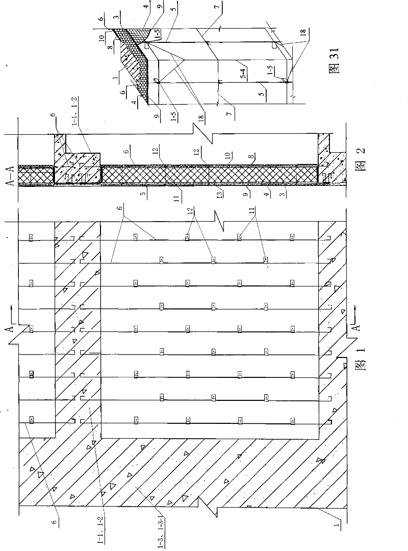
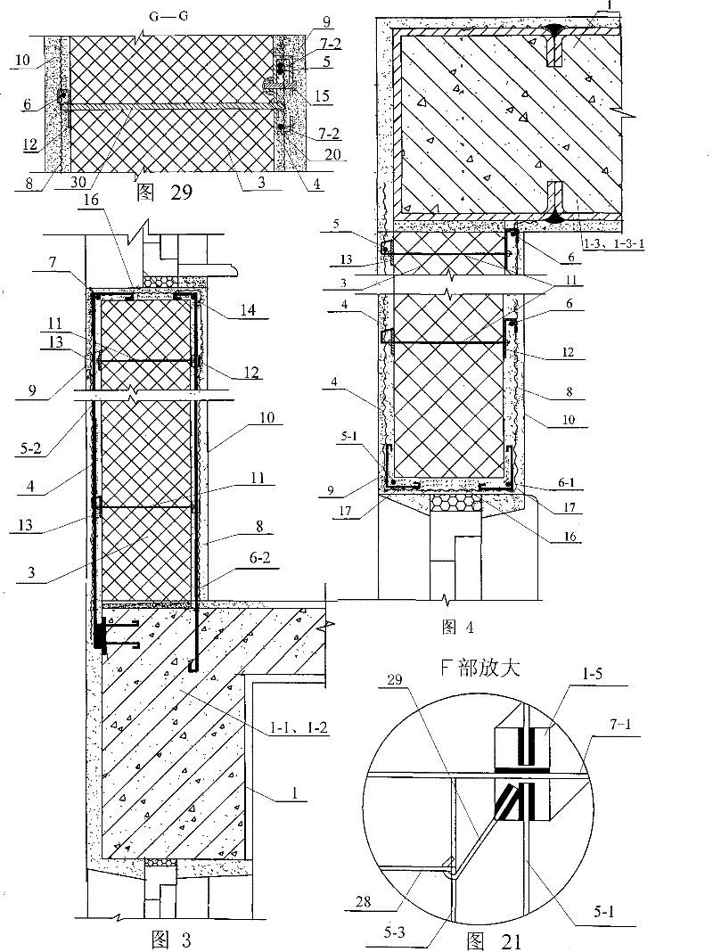
[0009] Specific implementation mode one: combine Figure 1 to Figure 6 Describe the embodiment, a structure of the composite wall of the present embodiment consists of the load-bearing member 1 of the main building structure, the core layer 3, the outdoor vertical reinforcement 5, the vertical reinforcement 5-1 at the side edge of the outdoor door and window, and the vertical reinforcement under the outdoor window sill. 5-2 reinforcement bars, 6 indoor vertical reinforcement bars, 6-1 vertical reinforcement bars at the side edge of indoor doors and windows, 6-2 vertical reinforcement bars under the indoor window sill, 7 horizontal horizontal reinforcement bars on the outdoor window sill, 14 horizontal reinforcement bars on the indoor window sill, 9 outer protective layers, and inner protective layers 10. The entrance protection layer 16 is composed; the load-bearing member 1 of the main structure of the building is a beam 1-1, a cantilevered plate 1-2, a column 1-3 or a short-l...

specific Embodiment approach 2

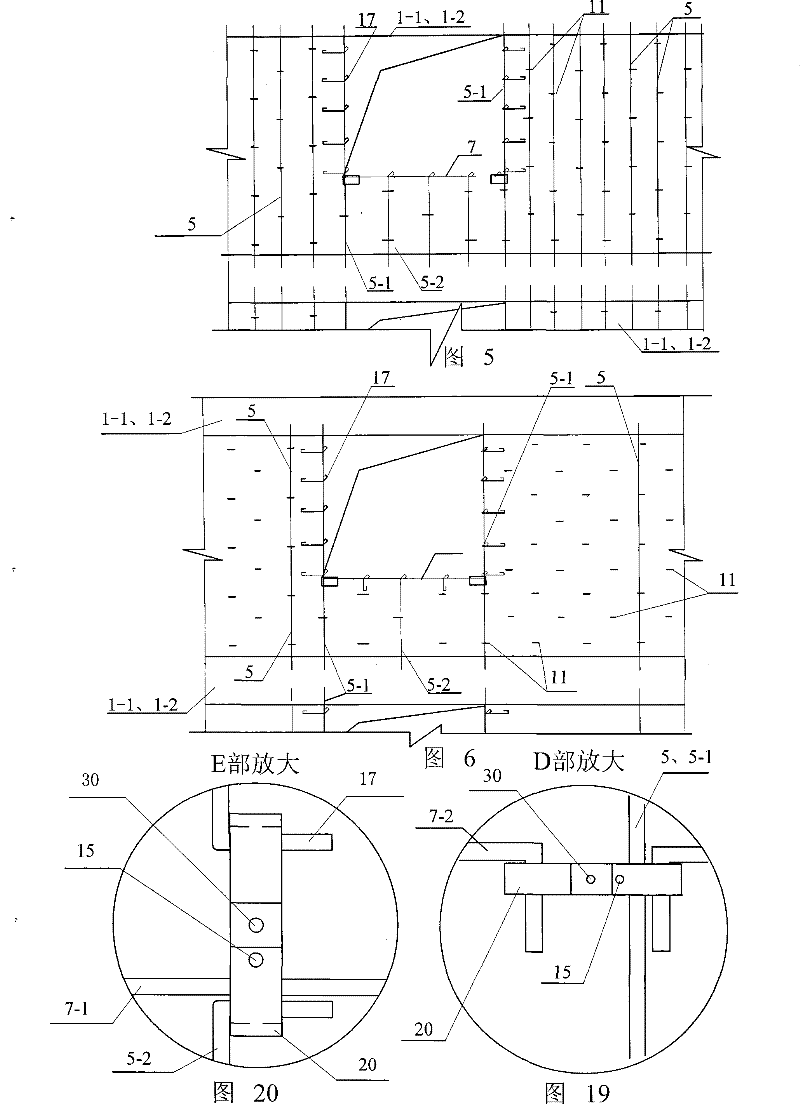
[0011] Specific implementation mode two: combination Figure 1 to Figure 6 Describe this embodiment, the difference between this embodiment and specific embodiment 1 is: this embodiment also adds internal and external pull-connected steel wires 11, a first steel gasket 12, and a second steel gasket 13; Gasket 12 is fixedly connected with indoor vertical steel bars 6, vertical steel bars 6-2 under indoor window sills, and vertical steel bars 6-1 at the side edges of indoor doors and windows with hooks. The core layer 3 is attached to the first steel gasket 12. One end of the steel wire 11 passes through the first steel gasket 12, the core layer 3 and the second steel gasket 13 sequentially from the inside to the outside. Steel bar 5, vertical steel bar 5-2 under the outdoor window sill and vertical steel bar 5-1 on the side edge of the outdoor door and window are fixedly connected. When the core layer 3 is a polymer insulation board, it is advisable to adopt this embodiment. T...

specific Embodiment approach 3

[0012] Specific implementation mode three: combination Figure 1 to Figure 6 Describe this embodiment. The difference between this embodiment and the second embodiment is that this embodiment also adds an outdoor metal mesh 4; 1. The inner side or outer side of the vertical steel bar 5-2 under the outdoor window sill is bound and fastened, and the outer end of the inner and outer tension connecting steel wire 11 is bent and hooked to the outdoor vertical steel bar 5, and the vertical steel bar 5-2 under the outdoor window sill and / or inner and outer pull The outer ends of the steel wires 11 are bent and hooked to the outdoor metal mesh 4 for fastening and connection, and the outdoor metal mesh 4 is tied and connected with the horizontal horizontal steel bar 7 of the outdoor window sill and the vertical steel bar 5-1 at the side edge of the outdoor door and window at the opening of the door and window, and bent Fold into the room and connect with 6-1 vertical steel bar on the s...


PUM


Abstract

The invention discloses a composite wall provided with reinforced bars and / or metal mesh plaster on the inner and the outer sides or the both sides, and relates to a building composite wall, aiming at the problem that the prior binding composite insulating wall has incomprehensive structural form. Proposal one: outdoor vertical reinforced bars (5) and indoor vertical reinforced bars (6) are fixed and connected with the outside and the inside of load bearing components (1) of the main structure of the building, and the inner side and the outer side of a sandwich layer (3) are provided with an inner protection layer and an outer protection layer; proposal two: vertical reinforced bars (5-2) under an outdoor window sill and vertical reinforced bars (6-2) under an indoor window sill are fixed and connected with overhanging plates (1-2); proposal three: the indoor vertical reinforced bars (6) arranged on the two sides of the sandwich layer 3 are fixed and connected with the load bearing components (1) of the main structure of the building; proposal four: the inner sides and the outer sides of the indoor vertical reinforced bars (6) on the two sides of an air layer and an indoor metal mesh are provided with protective layers (10-1), and the air layer (3-1) is positioned between the protective layers (10-1) on the two sides. The invention has the advantages that the shock resistance is good, the wind proof load is good, the fabricating cost is low, the security of the outer decoration surface layer is good, the indoor usable area is increased, and the requirements on low energy consumption buildings are met.

Description

technical field [0001] The invention relates to a building composite wall. Background technique [0002] For thousands of years, human society has used brittle materials such as stones, bricks, blocks, and concrete as walls except for wooden structures. In the world, the population is increasing rapidly, there are more and more high-rise buildings, and people are demanding higher and higher levels of comfort. Today, with energy shortages and serious environmental pollution, these traditional walls have highlighted the shortcomings of poor thermal insulation, energy saving, and poor earthquake resistance, and firing red bricks consumes a lot of arable land. [0003] The exterior walls of buildings in heating areas are like our cotton-padded clothes in winter, and the exterior walls of buildings in hot summer areas are like the shell of refrigerators. In order to save energy in buildings, in the past 30 years, Europe and the United States have successively studied and applied...

Claims


Application Information

Patent Timeline
Patent Type & Authority Patents(China)
IPC IPC(8): E04B1/76E04B2/00E04B1/00E04F13/00
Inventor 吴淑环
Owner 吴淑环
Why Eureka
Try Eureka