Sliding face modification material, method for producing sliding face modification material, method for using sliding face modification material, sliding members, and compressor
A technology for modifying materials and sliding components, applied in the field of compressors, can solve problems such as insufficient reduction of sliding loss and decline in wear resistance, and achieve the effects of preventing powder agglomeration and preventing energy loss from increasing.
- Summary
- Abstract
- Description
- Claims
- Application Information
AI Technical Summary
Problems solved by technology
Method used
Image


Examples
Embodiment approach 1
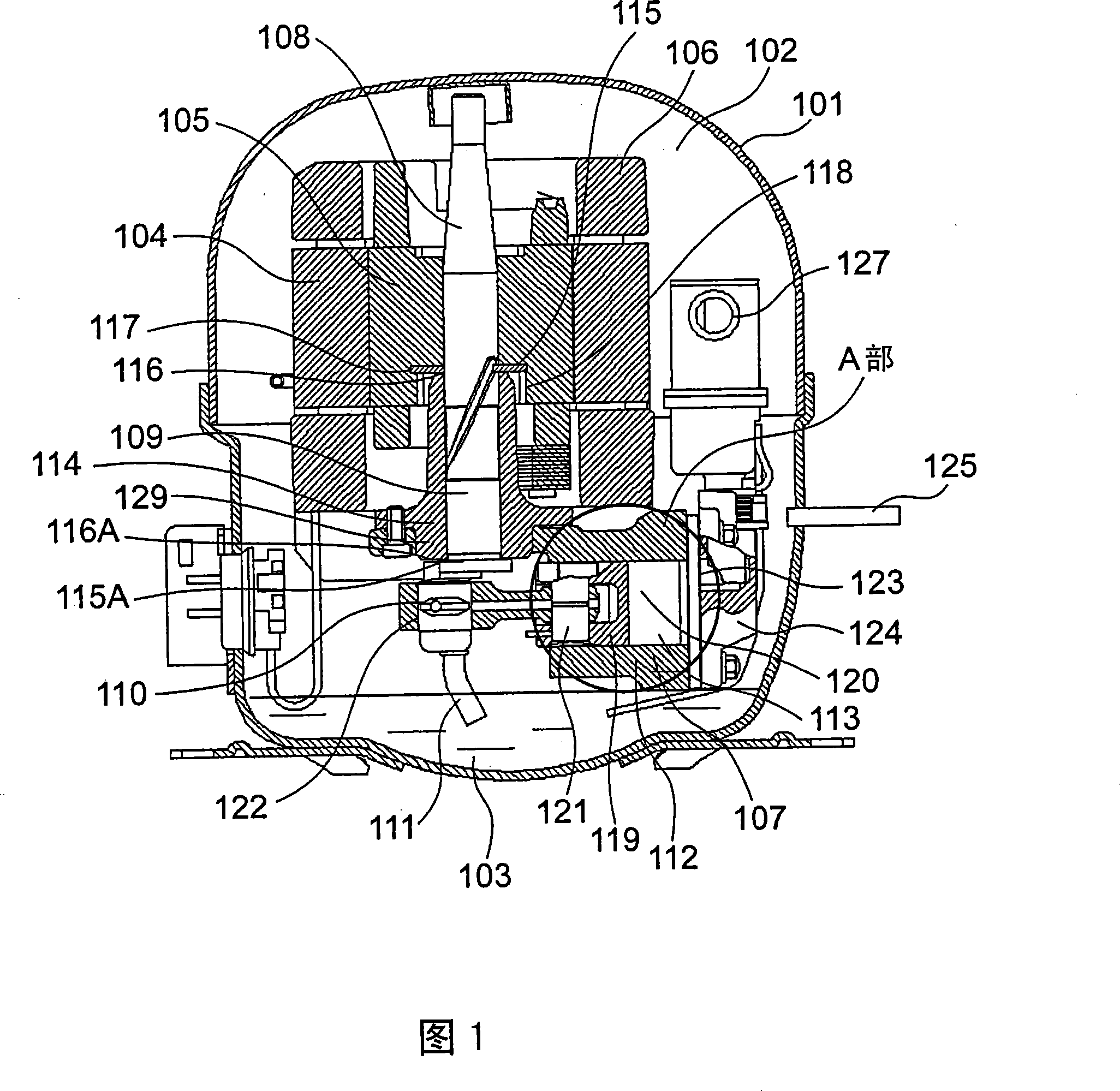
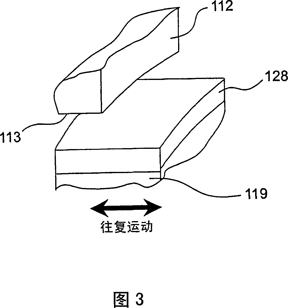
[0103] Fig. 1 is a longitudinal sectional view showing the internal structure of a reciprocating compressor according to Embodiment 1 of the present invention. Fig. 2 is an enlarged cross-sectional view of a portion indicated by symbol A in Fig. 1 . FIG. 3 is an enlarged schematic diagram showing a portion indicated by symbol B in FIG. 2 and shown in a perspective cutaway. FIG. 4 is a diagram schematically showing a method of forming a coating layer of a sliding portion of the compressor according to Embodiment 1. FIG.
[0104] In FIG. 1 , a refrigerant 102 composed of R600a or R134a is filled in an airtight container 101 , and oil 103 is stored at the bottom thereof. In addition, an electric element 106 including a stator 104 and a rotor 105 , and a reciprocating compression element 107 driven by the electric element 106 are housed in the airtight container 101 . Compression element 107 sucks and compresses refrigerant 102 introduced into airtight container 101 through suct...
Embodiment approach 2
[0155] Next, a rolling piston compressor according to Embodiment 2 of the present invention will be described with reference to the drawings.
[0156] Fig. 5 is a longitudinal sectional view of a rotary piston compressor according to Embodiment 2 of the present invention. FIG. 6 is a cross-sectional view taken along line VI-VI of FIG. 5 . Fig. 7 is an enlarged perspective view of part E in Fig. 6 .
[0157] In FIGS. 5 and 6, refrigerant 202 is sealed in airtight container 201, and electric element 205 composed of stator 203 and rotor 204 and rotary plunger type compression element 206 driven by electric element 205 are housed together with oil 207. .
[0158] The compression element 206 includes: a shaft 211 driven by the electric element 205, a cylinder 213 penetrating through the shaft 211, a main bearing 214 fixed on the surface of the electric element side as one surface of the cylinder 213, and a main bearing 214 fixed on the other surface of the cylinder 213. The auxi...
Embodiment approach 3
[0195] Next, a reciprocating compressor according to Embodiment 3 of the present invention will be described with reference to the drawings. The internal configuration of the reciprocating compressor according to Embodiment 3 has substantially the same configuration as that of the compressor according to Embodiment 1 shown in FIG. 1 described above. Therefore, the compressor according to Embodiment 3 will be described using FIG. 1 .
[0196] Fig. 8 is an enlarged sectional view of a part corresponding to the part indicated by symbol A in the compressor shown in Fig. 1 . FIG. 9 is an enlarged perspective view of a portion indicated by symbol C in FIG. 8 . FIG. 10 is a diagram schematically showing a method of forming a coating layer of a sliding portion of a compressor according to Embodiment 3. FIG. 11 is a graph showing the relationship between the amount of moisture contained in a molybdenum disulfide projection material as a sliding surface modifying material and the film ...
PUM
| Property | Measurement | Unit |
|---|---|---|
| particle size | aaaaa | aaaaa |
| particle size | aaaaa | aaaaa |
| particle size | aaaaa | aaaaa |
Abstract
Description
Claims
Application Information
 - R&D
- Intellectual Property
- Life Sciences
- Materials
- Tech Scout
- Unparalleled Data Quality
- Higher Quality Content
- 60% Fewer Hallucinations
Browse by: Latest US Patents, China's latest patents, Technical Efficacy Thesaurus, Application Domain, Technology Topic, Popular Technical Reports.
© 2025 PatSnap. All rights reserved.Legal|Privacy policy|Modern Slavery Act Transparency Statement|Sitemap|About US| Contact US: help@patsnap.com