
Down-hole forward looking phase controlled sound wave imaging method and imaging device

An imaging method and imaging device technology, applied in earthwork drilling, wellbore/well components, measurement, etc., to achieve the effects of improving work efficiency, reducing labor intensity, and reducing costs

Inactive Publication Date: 2008-02-13
INST OF ACOUSTICS CHINESE ACAD OF SCI
View PDF0 Cites 16 Cited by
  • Summary
  • Abstract
  • Description
  • Claims
  • Application Information

AI Technical Summary

Problems solved by technology

These problems cannot be solved by existing downhole detectors, and new acoustic detection methods and technologies need to be studied to meet the urgent needs of oil and gas engineering

Method used


Image

  • Down-hole forward looking phase controlled sound wave imaging method and imaging device
  • Down-hole forward looking phase controlled sound wave imaging method and imaging device
  • Down-hole forward looking phase controlled sound wave imaging method and imaging device

Examples


Embodiment 1

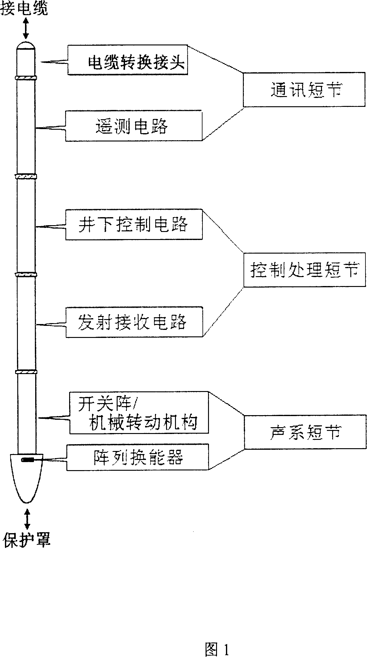
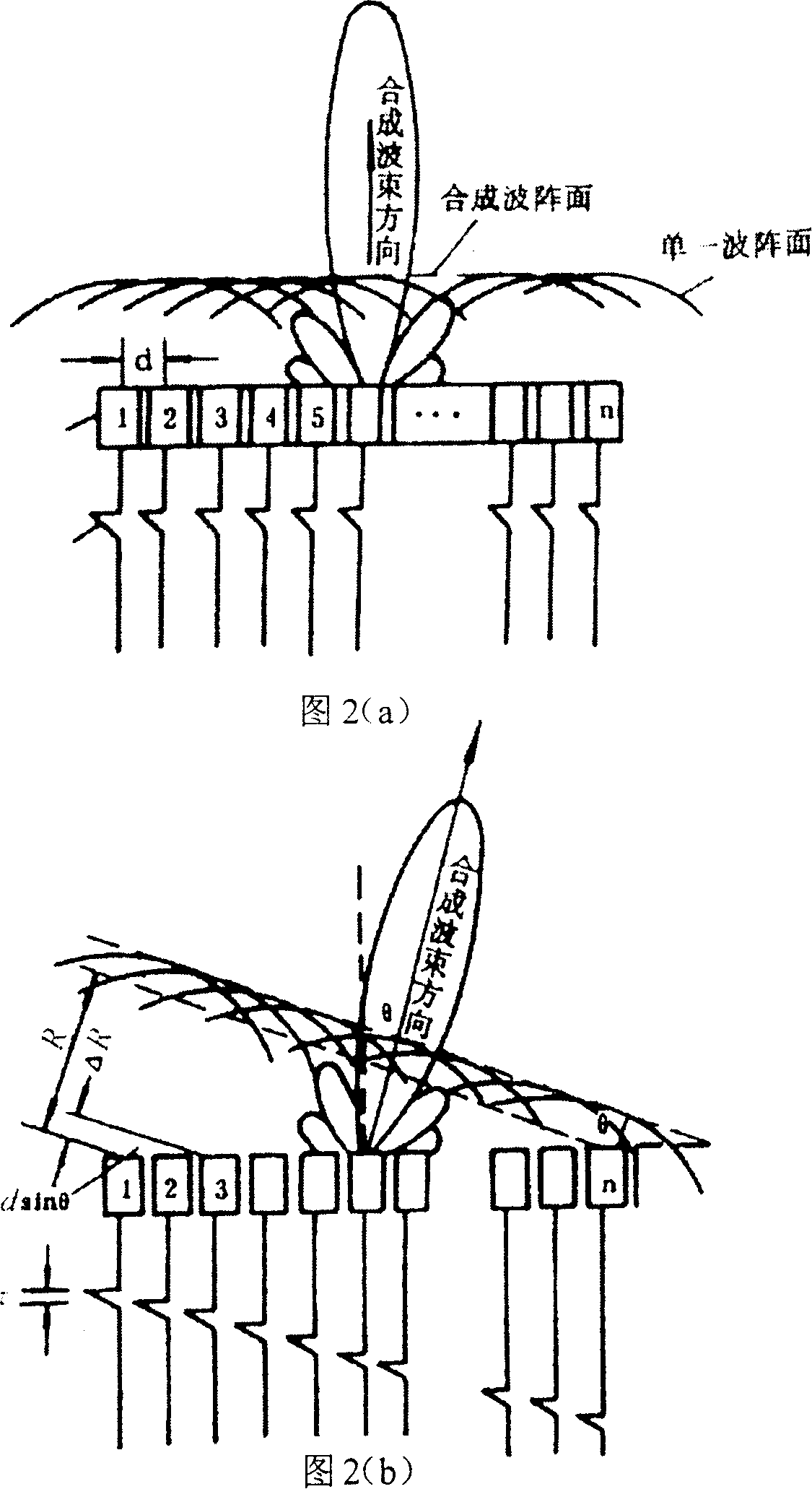
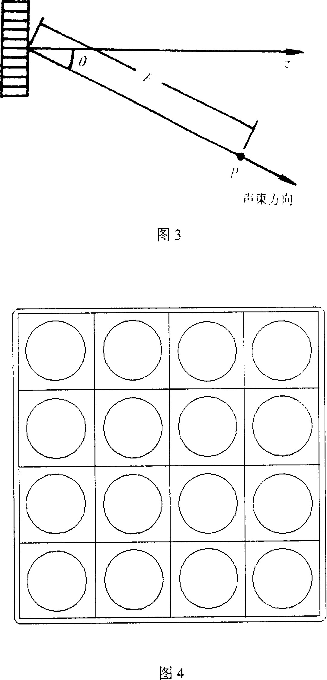
[0043] As shown in FIG. 1 , the entire phase-controlled acoustic wave imaging device generally consists of two parts: a downhole system and a surface system, and the communication between the two is carried out through a logging cable 21 . The downhole system consists of three parts: acoustic sub-section, control sub-section and communication sub-section, and the mechanical skeleton provides support and protection for the entire downhole system. The area array or linear array ultrasonic transducer (will be described in detail in embodiment 2), which is the core component of the phased acoustic wave imaging detector, is placed in the acoustic system subsection, and if necessary, there is an accompanying switch array or mechanical rotation mechanism, Responsible for the transmission and reception of acoustic signals. The control processing section is composed of ultrasonic transmitting circuit, receiving circuit, timing controller, central processing unit, A / D acquisition circui...

Embodiment 2

[0057] In Example 1, the area array transducer is used, and the phase control technology is used to directly form a three-dimensional sound beam, so that the three-dimensional image under the logging tool can be obtained directly. In this embodiment, a linear array ultrasonic transducer is used, and the two-dimensional cross-sectional image directly below the transducer array is obtained by using the principle of phased scanning, and then the linear array ultrasonic transducer is controlled to rotate around the well axis through a mechanical rotation mechanism to obtain A series of two-dimensional cross-sectional images corresponding to different deflection angles are superimposed to obtain a three-dimensional stereoscopic image. The advantage of this scheme is that the number of array elements is relatively small, the processing circuit and beamforming are relatively easy, and the imaging resolution is high.

[0058] As shown in Figure 6, on the basis of Embodiment 1, the dow...


PUM


Abstract

The invention discloses a front-view and phase control sound wave imaging method and device in a well. The method comprises the following: (1) all array elements are triggered to make a linear array transducer form a one-direction scanning acoustic beam; (2) every array element receives a echo wave signal and transmits the signal to the ground system; (3) the direction of the scanning acoustic beam is changed until the data acquisition and transmission of the whole section under the linear array transducer is completed, and the ground system receives the scanning imaging data of the whole two-dimensional cross-section to complete a two-dimensional sectional image; (4) the linear array transducer rotates around a central axis at an angle to get another two-dimensional sectional image; (5) two-dimensional sectional images corresponding to each angle is got and are integrated into three-dimensional images. The imaging device comprises a power in the well, a cable descending into the well, a remote-detecting circuit, a central processor, a time schedule controller, a memory unit, an emitting unit, an A / D sample circuit, a linear array transducer, and a receiving circuit. The invention is provided with the advantage of being direct, accurate and highly efficient.

Description

technical field [0001] The invention relates to an ultrasonic imaging device, in particular to an ultrasonic imaging method and an imaging device suitable for detecting and imaging the front of downhole instruments. Background technique [0002] With the development of the economy, the position of petroleum as a strategic energy source becomes more and more important. Petroleum logging is known as the "eyes of the petroleum industry". High-tech engineering techniques that perform various tests on the formation are the only means by which people can accurately understand the structure and properties of the subsurface. Sonic logging is one of the most important logging methods. [0003] In the actual production of the oil field, the casing of the oil well will cause more and more losses to the oil and gas production due to stress, deformation and damage. Taking the oilfields affiliated to PetroChina as an example, by the end of 2002, the cumulative number of casing damaged ...

Claims


Application Information

Patent Timeline
Patent Type & Authority Applications(China)
IPC IPC(8): E21B47/00E21B47/002
Inventor 张海澜王秀明林伟军张澄宇王东吴楠
Owner INST OF ACOUSTICS CHINESE ACAD OF SCI
Learn More