Eureka AIR delivers breakthrough ideas for toughest innovation challenges, trusted by R&D personnel around the world.

Voltage buffer circuit for linear potentiostat

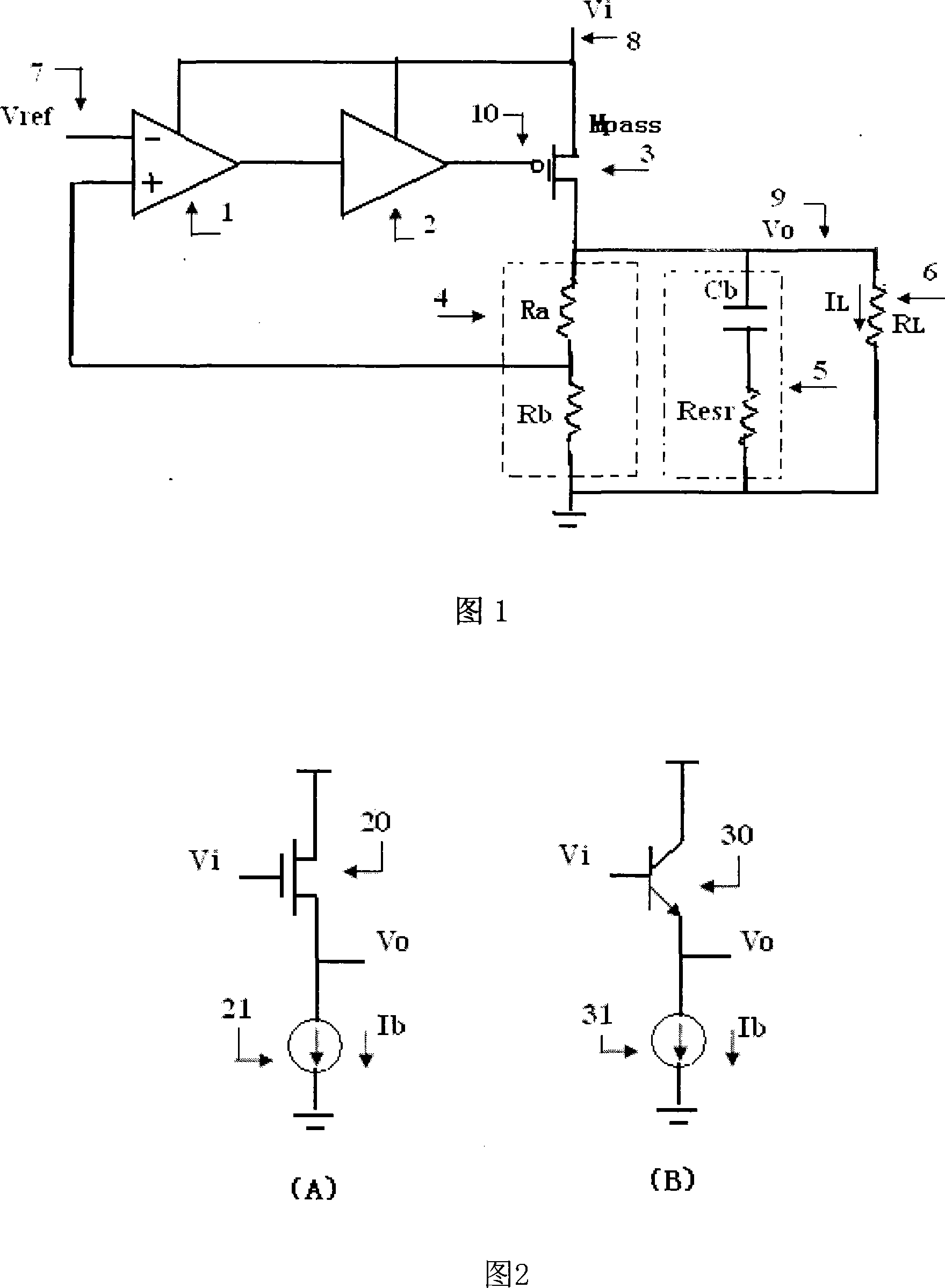
A technology of linear voltage regulator and voltage buffering, which is applied in the direction of instruments, adjusting electric variables, control/regulation systems, etc., can solve the problems of occupation, large chip area, etc., and reduce the influence of transient response and noise suppression ability, The effect of saving chip area, reducing cost and difficulty of use

Inactive Publication Date: 2008-01-16
CHINA AEROSPACE TIMES ELECTRONICS CORP NO 771 RES INST
View PDF0 Cites 25 Cited by
  • Summary
  • Abstract
  • Description
  • Claims
  • Application Information

AI Technical Summary

Problems solved by technology

However, on-chip frequency compensation requires a large amount of on-chip capacitance (generally greater than 10pF), which occupies a large chip area

Method used


Image

  • Voltage buffer circuit for linear potentiostat
  • Voltage buffer circuit for linear potentiostat
  • Voltage buffer circuit for linear potentiostat

Examples


Embodiment Construction

[0059] The dynamic bias voltage buffer circuit for linear voltage regulator of the present invention can dynamically adjust the bias current of the voltage buffer circuit by monitoring the output current of the regulator tube, thereby changing the output resistance of the voltage buffer circuit, so that the pole of the output terminal of the voltage buffer circuit The change follows the change of the pole at the output terminal of the voltage regulator circuit to ensure the stability of the system. In the specific implementation of the dynamic bias voltage buffer circuit, through the design of the specific device size, the dynamic bias current of the voltage buffer circuit is guaranteed, and a very small "copy" or "mirror image" of the voltage regulator tube current is adjusted. ". In this way, when the linear regulator works in the no-load or light-load state, the bias current of the voltage buffer circuit is still at a static value, so the static power consumption of the lin...


PUM


Abstract

The invention relates to a voltage buffer circuit used in a linear voltage regulator. The circuit consists of a basic voltage buffer circuit, an output current monitoring circuit and a current mirror circuit; wherein the input end of the basic voltage buffer circuit is connected with the output end of a voltage difference amplifier of the linear voltage regulator which is also the output of a dynamic bias power source buffer circuit; the output end of the output current monitoring circuit is connected with the input end of the current mirror circuit; the output end of the current mirror circuit is in parallel connection with a static bias current source. Under the condition that the static power loss of voltage regulator circuit is not increased, the impact of a pole of the output end of the voltage buffer circuit to system phase margin and stability is reduced; the invention doesn't need the traditional linear voltage regulator and utilizes an outer wave filtering capacitance equivalent series resistance to generate zero point, which lowers the system cost, reduces use difficulty and reduces the impact of the equivalent series resistance to the transient state response and noise restraint capacity of the voltage regulator circuit; a chip upper frequency compensation capacitance is not needed, which saves chip area.

Description

technical field [0001] The invention relates to a semiconductor integrated circuit, in particular to a voltage buffer circuit inside a linear voltage regulator. Background technique [0002] In recent years, monolithic integrated linear regulated power supplies are widely used in battery-powered electronic systems, such as mobile phones, Consumer electronics such as handheld computers, as well as medical equipment and test instruments. [0003] The basic composition of a monolithic integrated linear regulator is shown in Figure 1, including a dropout amplifier (1), a voltage buffer (2), a voltage adjustment transistor (3) (pass transistor), and a feedback network (4). The reference voltage Vref(7) is a stable voltage signal generated internally or from outside the chip that does not change with temperature, input voltage, etc., and the capacitor Cb and its equivalent series resistance (5) and resistor RL(6) are integrated linear regulators The off-chip filter capacitor and...

Claims


Application Information

Patent Timeline
Patent Type & Authority Applications(China)
IPC IPC(8): G05F1/56
Inventor 汪西虎
Owner CHINA AEROSPACE TIMES ELECTRONICS CORP NO 771 RES INST
Why Eureka
Eureka Blog
Learn More