
Method for producing magnetic multilayer film

A manufacturing method and multilayer film technology, applied in the direction of magnetic thin film, application of magnetic film to substrate, manufacture/processing of electromagnetic devices, etc., can solve problems such as hindering the function of magnetic multilayer film

Active Publication Date: 2007-12-26
ULVAC INC
View PDF2 Cites 0 Cited by
  • Summary
  • Abstract
  • Description
  • Claims
  • Application Information

AI Technical Summary

Problems solved by technology

As a result, the surface of the magnetic multilayer film is damaged by etching, etc., hindering the function of the magnetic multilayer film.

Method used


Image

  • Method for producing magnetic multilayer film
  • Method for producing magnetic multilayer film
  • Method for producing magnetic multilayer film

Examples


Embodiment Construction

[0047] Embodiments of the present invention will be described below in conjunction with the accompanying drawings. In addition, in each drawing used for explanation below, in order to make the size of each component recognizable, the scaling ratio of each component is appropriately changed.

[0048] (Magnetic multilayer film)

[0049] First, a tunnel junction element including a TMR film, which is an example of a multilayer film including a magnetic layer, and an MRAM including the tunnel junction element will be described.

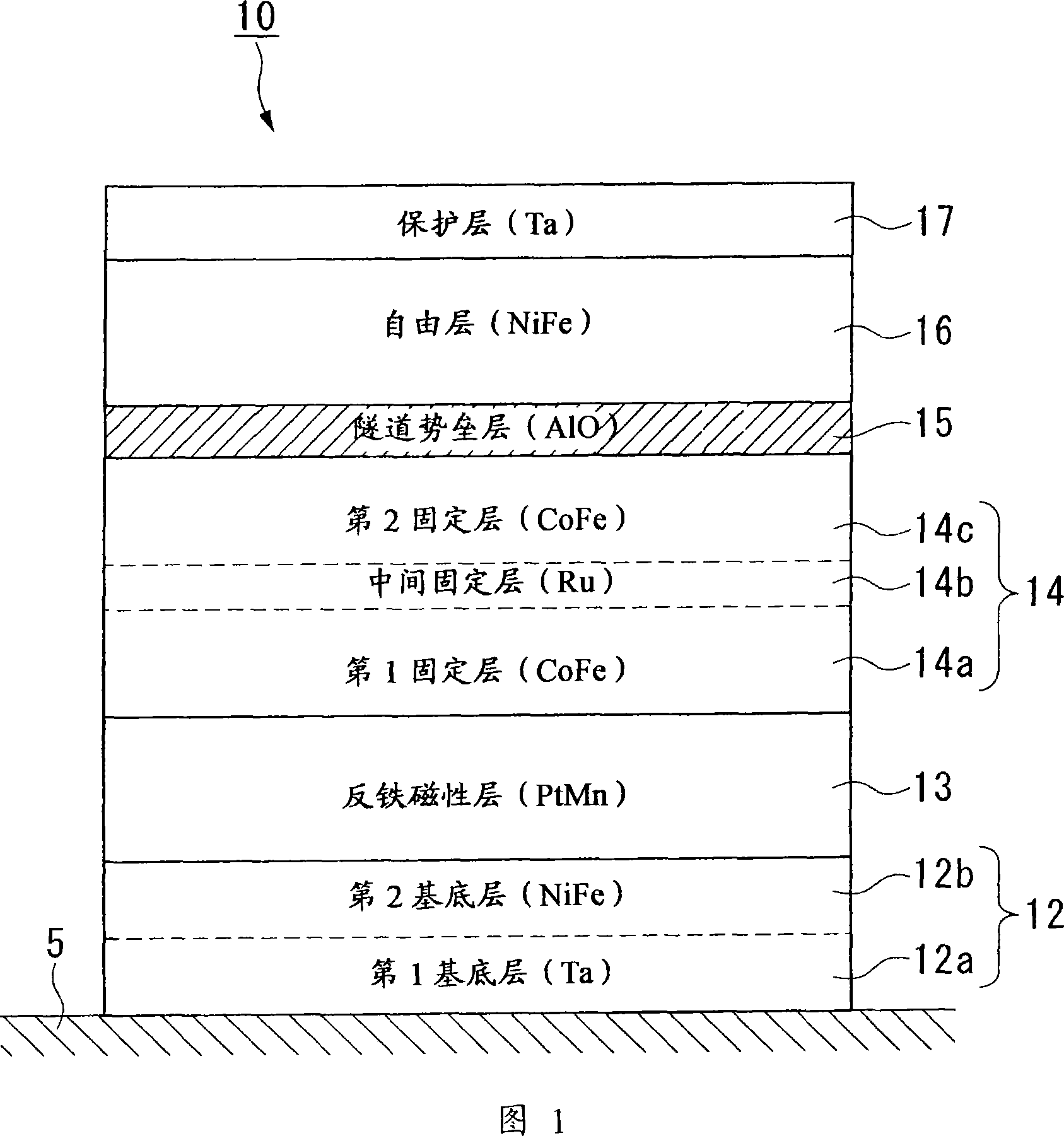
[0050] Figure 1 is a side sectional view of a tunnel engaging element. In the tunnel junction element 10 , an underlayer 12 is formed on the surface of the substrate 5 . The base layer 12 includes a first base layer 12a composed of Ta or the like and a second base layer 12b composed of NiFe or the like. An antiferromagnetic layer 13 composed of PtMn, IrMn, or the like is formed on the surface of the base layer 12 . The second base layer 12 b has a fun...


PUM


Abstract

Disclosed is a method for producing a magnetic multilayer film comprising a first magnetic layer formation step for forming a first magnetic layer on a substrate, a nonmagnetic layer formation step for forming a nonmagnetic layer on the first magnetic layer, and a second magnetic layer formation step for forming a second magnetic layer on the nonmagnetic layer. This method for producing a magnetic multilayer film is characterized in that it further comprises, before the nonmagnetic layer formation step, a plasma processing step wherein the substrate is placed in a plasma processing apparatus and processed with an inductively coupled plasma while being kept electrically insulated from the plasma processing apparatus.

Description

technical field [0001] The invention relates to a method for manufacturing a magnetic multilayer film, which is suitable for forming a film used to form a giant magnetoresistance (Giant Magnetic Resistive, GMR) spin valve or a tunneling magnetoresistance (Tunneling Magnetic Resistive, TMR) element The giant magnetoresistance spin valve is used to form a magnetic head, and the tunnel magnetoresistance element is used to form a magnetic random access memory (Magnetic Random Access Memory, MRAM). [0002] This application claims the priority of Japanese Patent Application No. 2005-000403 filed on January 5, 2005, the content of which is incorporated herein. Background technique [0003] Recently, an MRAM under development has a tunnel junction element composed of a TMR film. [0004] Figure 8A is a side sectional view of a tunnel engaging element. The tunnel junction element 10 is formed by laminating a first magnetic layer (pinned layer) 14 , a nonmagnetic layer (tunnel barr...

Claims


Application Information

Patent Timeline
IPC IPC(8): H01L43/12H01L27/105G11B5/39H01L43/08H01L21/8246H01F41/18
CPCG11B5/3909B82Y10/00B82Y25/00B82Y40/00G11B5/3163G11B5/3903H01F10/3254H01F10/3272H01F41/307H01L43/12H10N50/01H10B61/00
Inventor 菊地幸男森田正
Owner ULVAC INC
Learn More