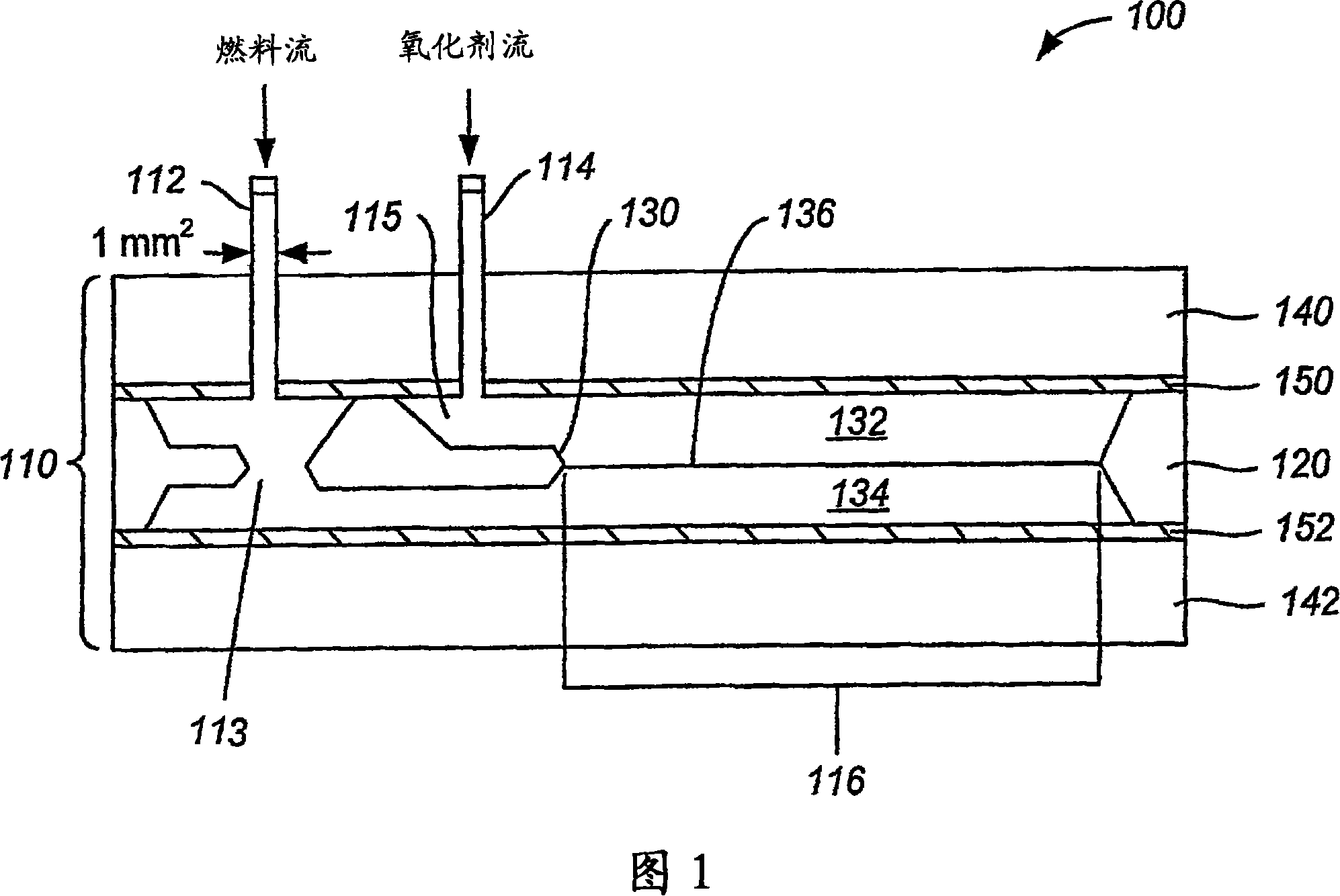
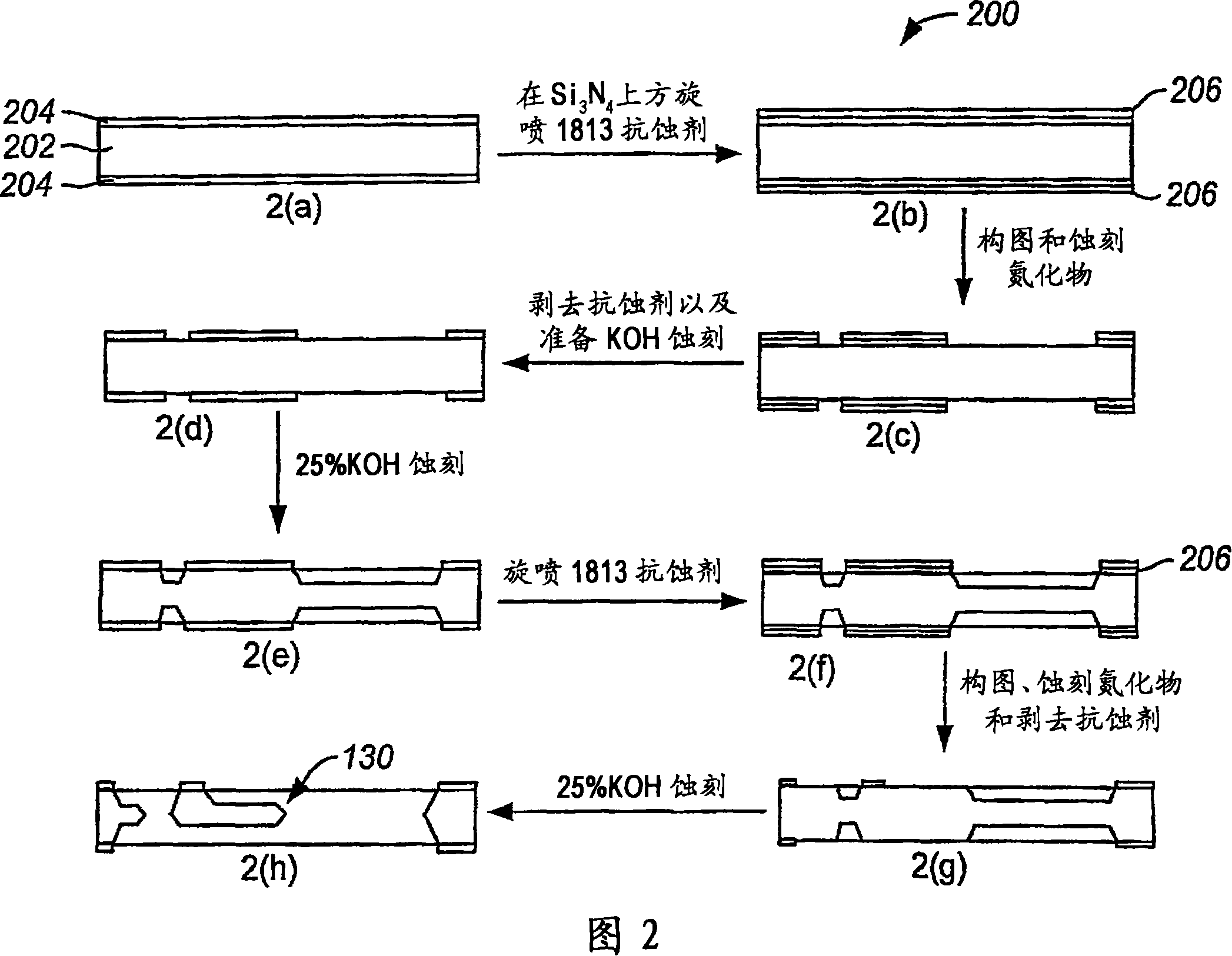
Planar membraneless microchannel fuel cell
A fuel cell and electrolyte technology, applied in the direction of aqueous electrolyte fuel cells, fuel cells, fuel cell additives, etc., can solve the problem of low thermodynamic potential
- Summary
- Abstract
- Description
- Claims
- Application Information
AI Technical Summary
Problems solved by technology
Method used
Image

Examples
Embodiment
[0113] Example: Fuel Cell Assembly
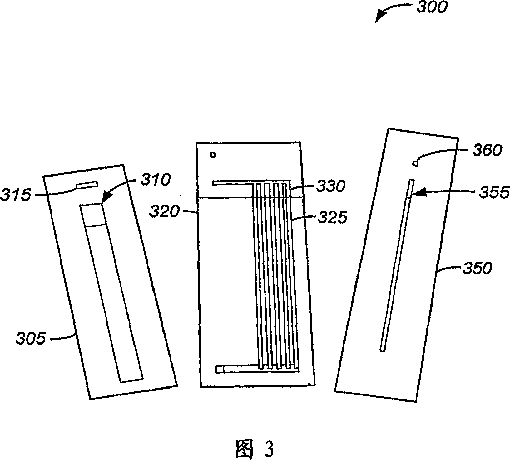
[0114] Having established that the proposed plate design generates laminar flow within the microchannels, the fabricated microchannels and electrodes were incorporated into fuel cell embodiments that illustrate various principles of the present invention, including providing insight into the system. Human control of parameters. Combine silicon microchannels in plexiglass cells with Kaptons on top or bottom of the microchannels Align the base platinum electrodes and clamp them together using bolts as shown in Figures 5 and 6.
[0115] FIG. 6 is a view showing an example of a silicon microchannel flow cell configured as a micro fuel cell 600 . In fuel cell 600, silicon microchannels 505 are provided. The two input tubes 510, 515 provide fluid entering the silicon microchannel 505 from the same side (ie from the top side of the embodiment shown in Figure 6). In the embodiment shown in FIG. 6, two input tubes 510 and 515 are attached to...
PUM
| Property | Measurement | Unit |
|---|---|---|
| mass | aaaaa | aaaaa |
| width | aaaaa | aaaaa |
| length | aaaaa | aaaaa |
Abstract
Description
Claims
Application Information
 - R&D
- Intellectual Property
- Life Sciences
- Materials
- Tech Scout
- Unparalleled Data Quality
- Higher Quality Content
- 60% Fewer Hallucinations
Browse by: Latest US Patents, China's latest patents, Technical Efficacy Thesaurus, Application Domain, Technology Topic, Popular Technical Reports.
© 2025 PatSnap. All rights reserved.Legal|Privacy policy|Modern Slavery Act Transparency Statement|Sitemap|About US| Contact US: help@patsnap.com