Novel method for determining optical fiber parameter

A technology of optical fiber parameters and determination methods, which is applied to clad optical fibers, light guides, optics, etc., can solve problems such as large insertion loss, poor control of refractive index distribution, and increased cost, and achieve the effect of large dispersion compensation

Inactive Publication Date: 2007-12-05
UNIV OF ELECTRONICS SCI & TECH OF CHINA
View PDF0 Cites 8 Cited by
  • Summary
  • Abstract
  • Description
  • Claims
  • Application Information

AI Technical Summary

Problems solved by technology

[0009] Although the dispersion compensating fiber (DCF) compensation method has the above advantages, it should be noted that the compensation amount per unit length of DCF is low, and the dispersion compensation value of DCF per kilometer is generally on the order of hundreds of ps / nm
In addition, the insertion loss of DCF is relatively large. After dispersion compensation, an optical amplifier is required to compensate the loss, which increases the cost.
In addition, compared with standard optical fibers, DCF has a thinner core diameter and a larger refractive index difference, so the refractive index distribution is not easy to control, and the production is more difficult.

Method used


Image

  • Novel method for determining optical fiber parameter
  • Novel method for determining optical fiber parameter
  • Novel method for determining optical fiber parameter

Examples


Embodiment 1

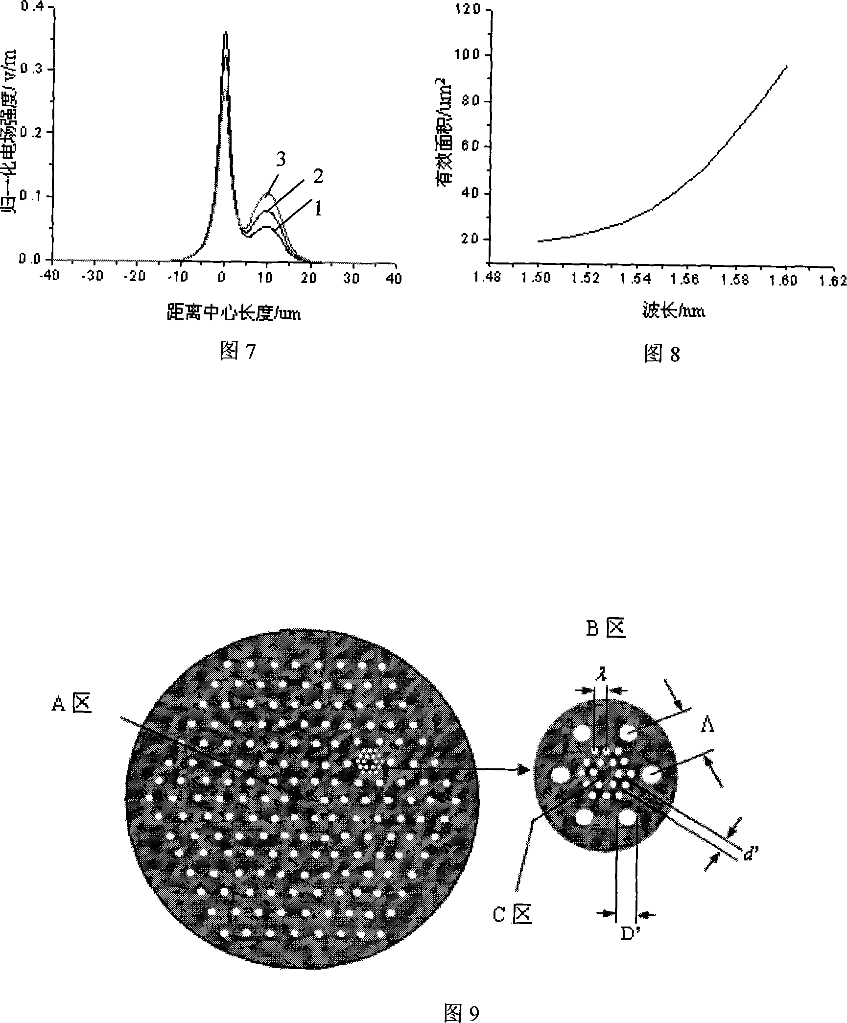
[0056] Referring to the photonic crystal fiber structure of solid light guide, it is composed of quartz and air holes in the cladding, which can be regarded as the quartz in the center surrounded by air holes. In view of this, the present invention calls such a structure a light guide unit, the central solid part is called a central optical waveguide area (core), and the peripheral air hole and its surrounding areas are called an external field area. As shown in FIG. 9 , the center is the central optical waveguide area, and the outer area with air holes is the outer field area.

[0057] See Figure 9. This embodiment includes a first light guide unit and a second light guide unit, and the second light guide unit is distributed in the outer field area of ​​the first light guide unit and is surrounded by air holes of the first light guide unit. The structures of the first and second light guide units are arranged in the manner of photonic crystal fiber, that is, both are in the ...


PUM


Abstract

The invention discloses an affirming method of new-typed optical fiber parameter through grouped intelligent evolution algorism in the optical fiber communicating technique, which is characterized by the following: adopting Raman amplifier gain dielectric optical fiber to affirm the parameter; changing the effective fiber core area Aeff and Raman gain factor gR synchronously; keeping Raman gain factor gR equal gR / Aeff as approximate constant within certain wave band; providing gain dielectric for flat Raman amplifier with high gain, low extraction light running power, broad band gain spectrum. The invention has large dispersion supplementing quantity of unit length, which realizes dispersion slope design of the ordered dispersion.

Description

technical field [0001] The invention relates to optical fiber communication technology. Background technique [0002] Fiber Raman amplifier (fiber Raman amplifier, FRA) has been recognized as a large-capacity dense wavelength division multiplexing (DWDM), long-distance One of the key technologies of (long-haul, LH) and ultra-long-haul (ULH) optical fiber transmission systems. [0003] When FRA is applied in the DWDM optical fiber communication system, it is a basic requirement to have better gain flatness in a wider operating band, because the flatness of the optical gain of each signal has an impact on the optical signal-to-noise ratio (OSNR) In addition, the large power difference between the various signal lights will increase the crosstalk at the output of the DWDM channel demultiplexer, so the FRA used in the DWDM optical fiber communication system should have flat broadband gain. However, since the Raman gain coefficients of various optical fibers currently used as F...

Claims


Application Information

Patent Timeline
Patent Type & Authority Applications(China)
IPC IPC(8): G02B6/02G02B6/00
Inventor 姜海明
Owner UNIV OF ELECTRONICS SCI & TECH OF CHINA
Why Eureka
Try Eureka