
Worm wheel and worm with dynamic and static pressure lubricating at engagement zone

A worm gear, dynamic and static pressure technology, applied to components with teeth, gear lubrication/cooling, transmission devices, etc., can solve the problems of limited application range, wear of worm gears, low transmission efficiency, etc., and achieve less heat generation and high transmission efficiency Improve and improve the effect of lubrication conditions

Inactive Publication Date: 2007-11-07
刘继清
View PDF1 Cites 11 Cited by
  • Summary
  • Abstract
  • Description
  • Claims
  • Application Information

AI Technical Summary

Problems solved by technology

The usual worm gear has the advantages of large speed ratio, simple or compact structure, etc. Its lubrication method is divided into oil pool for immersion lubrication and oil pump to the meshing area for lubrication. The relative sliding speed between the meshing surfaces of the worm gear and worm is large, and the worm driven The lubricating oil has a strong centrifugal effect, which makes the conditions for the formation of the oil film in the meshing area poor. In addition to the oil churning loss of the worm, the worm gear of this general structure has the disadvantages of serious wear, low transmission efficiency and serious heat generation, which makes the worm gear drive The scope of application is limited

Method used


Image

  • Worm wheel and worm with dynamic and static pressure lubricating at engagement zone
  • Worm wheel and worm with dynamic and static pressure lubricating at engagement zone
  • Worm wheel and worm with dynamic and static pressure lubricating at engagement zone

Examples


Embodiment Construction

[0014] The specific implementation manners of the present invention will be further described in detail below in conjunction with the accompanying drawings.

[0015] The worm gear with dynamic and static pressure lubrication in the meshing area of ​​the present invention is a new type of worm gear formed by improving the known worm gear.

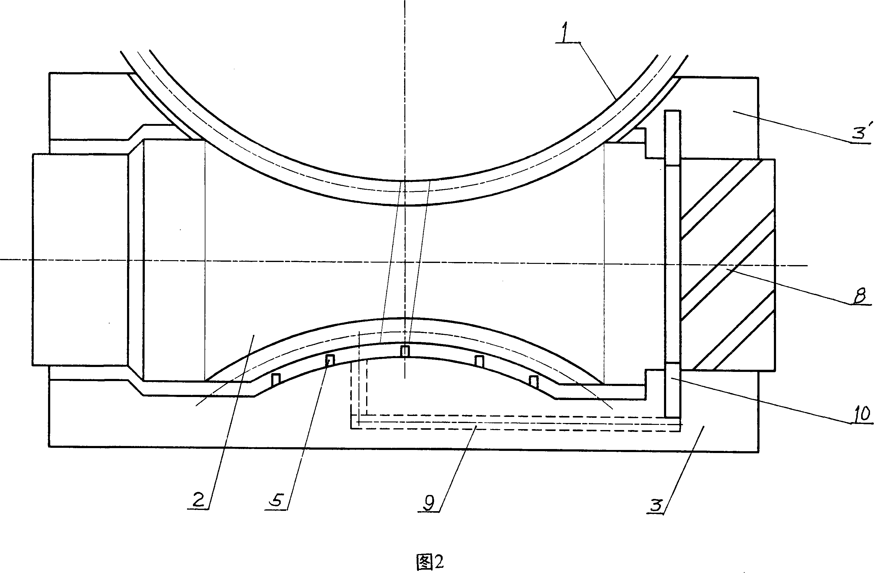
[0016] As shown in Figure 1, a sealing block 3 or 3' is installed on the periphery of the meshing section of the worm wheel 1 and the worm screw 2, and the sealing block 3 or 3' can seal the meshing section of the worm wheel 1 and the worm screw 2. The opposite surfaces between the sealing block 3 and the sealing block 3' can be connected by bonding or bolts. There is a sealing strip 4 or 4' at the contact between the seal block 3 or the seal block 3' and the worm gear 1, and there are labyrinth teeth 5 between the seal block 3 and the worm 2 opposite surfaces or between the seal block 3' and the worm 2 opposite surfaces, and the labyrinth t...


PUM


Abstract

The invention discloses the worm and gear with the active and static pressure lubricant used in the mechanically-driven meshing zone. The sealing mass is installed in the out of the meshing zone of the worm and the gear, which contacts with the worm and has the sealing strip. The maze tooth is on the relative surface of the sealing mass and the gear, which is directed to the bear without the oil through the oil pipe from the oil hole opened in the sealing zone formed between the sealing mass hollow and the worm or gear. The screw vanes with the same direction are set on the meshed end of the basal leptospira in gear. The ring oil groove in sealing mass hollow is connected to the sealing zone through the oil hole; on the tooth surface of the worm or gear, the unconnected oil slots are opened. The structure of the invention has improved the lubricant of the worm and gear to improve the loading ability. The driven efficiency has improved by 3%, so it can instead the multilevel gear or planet gear and used in the big speed ratio field.

Description

technical field [0001] The invention relates to a worm gear and worm with dynamic and static pressure lubrication in the meshing area of ​​mechanical transmission. Background technique [0002] Worm gear is a known basic transmission mechanism, such as the "worm gear" whose application number is 200410023788.4 (CN1563747A). The usual worm gear has the advantages of large speed ratio, simple or compact structure, etc. Its lubrication method is divided into oil pool for immersion lubrication and oil pump to the meshing area for lubrication. The relative sliding speed between the meshing surfaces of the worm gear and worm is large, and the worm driven The lubricating oil has a strong centrifugal effect, which makes the conditions for the formation of the oil film in the meshing area poor. In addition to the oil churning loss of the worm, the worm gear of this general structure has the disadvantages of serious wear, low transmission efficiency and serious heat generation, which ...

Claims


Application Information

Patent Timeline
Patent Type & Authority Applications(China)
IPC IPC(8): F16H1/16F16H55/22F16H57/04
Inventor 刘继清
Owner 刘继清
Learn More