
A portable apparatus for suppling cutting oil

A technology for supplying devices and cutting oil, which is used in sports accessories, metal processing machinery parts, maintenance and safety accessories, etc., and can solve problems such as failure rate and inability to transfer.

Inactive Publication Date: 2007-10-24
李美子
View PDF1 Cites 1 Cited by
  • Summary
  • Abstract
  • Description
  • Claims
  • Application Information

AI Technical Summary

Problems solved by technology

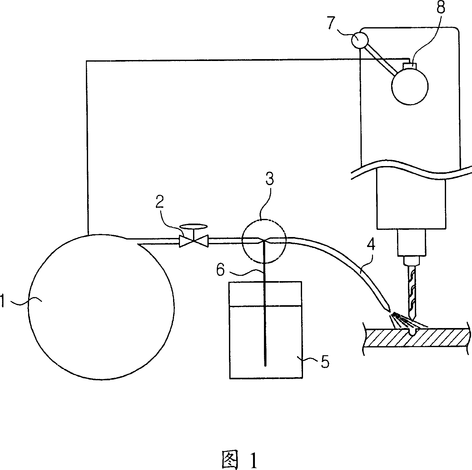
[0010] However, in the above-mentioned cutting oil supply device, since the cutting oil is mixed at the mixing part 3 and then transferred by the air compression of the air compressor, it is not effective in jetting cutting oil with high viscosity.
[0011] In addition, the transfer tube 4 for spraying cutting oil and the computer-aided manufacturing switch 8 cannot be detached from the machine tool, and there is a problem that transfer to the required place cannot be performed.

Method used


Image

  • A portable apparatus for suppling cutting oil
  • A portable apparatus for suppling cutting oil
  • A portable apparatus for suppling cutting oil

Examples


Embodiment Construction

[0039] An effective embodiment of the present invention is described in detail with reference to the accompanying drawings as follows:

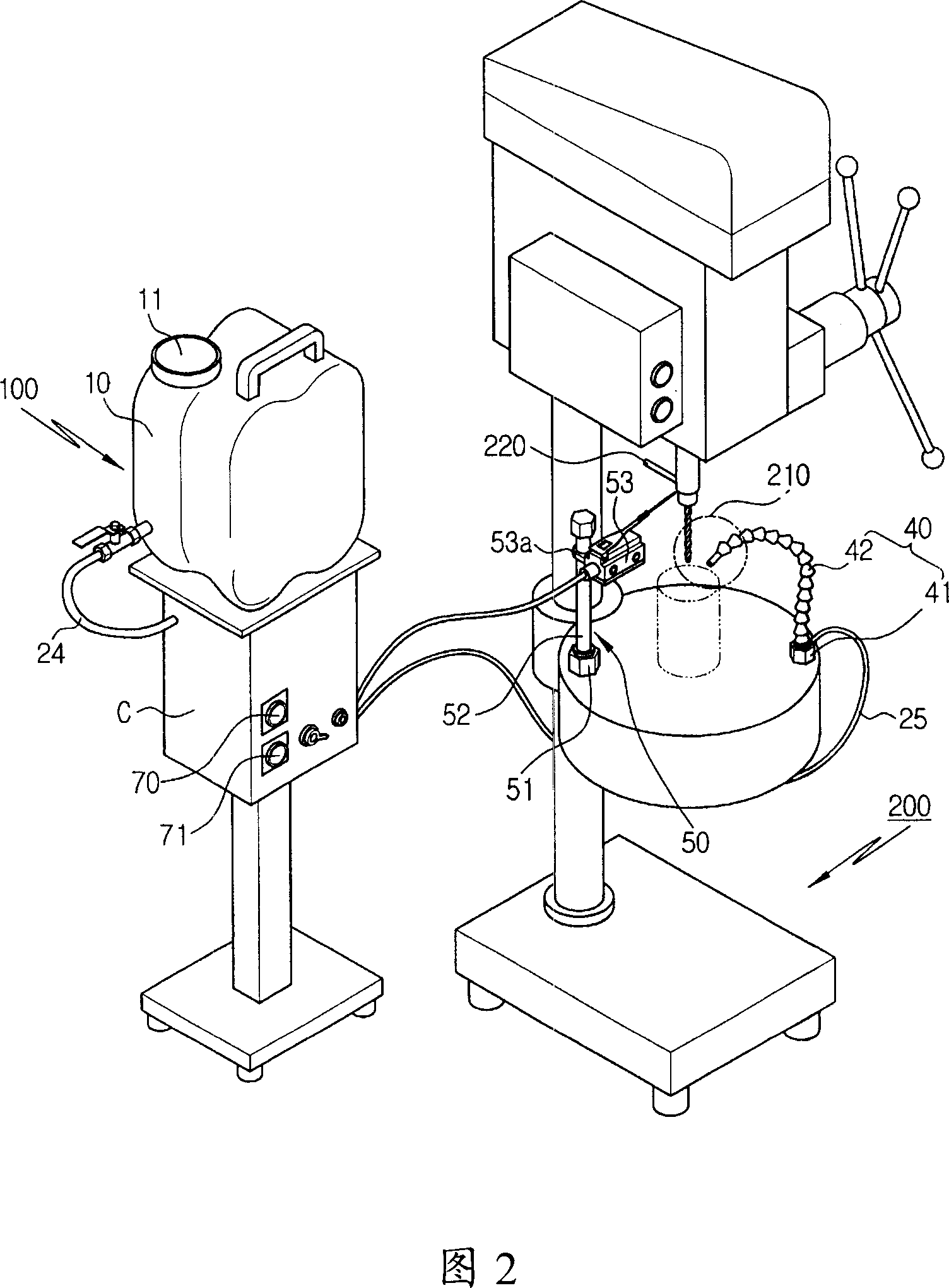
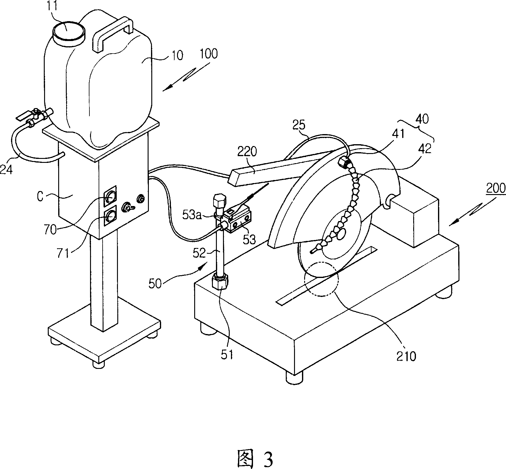
[0040] Fig. 2 is a perspective view of setting the mobile cutting oil supply device of the present invention on a working instrument; Fig. 3 is a perspective view of setting the mobile cutting oil supply device of the present invention on other working instruments; Fig. 4 is a perspective view showing the mobile cutting oil supply device of the present invention The voltage control circuit diagram of the entire structure of the oil supply device.

[0041] As shown in the figure, the mobile cutting oil supply device 100 of the present invention can be installed on any kind of working equipment. Such as: drilling machine, desktop milling machine, grinding machine, grinding machine, cutting machine, circular cutting machine, stamping continuous roller feeder, chipper, etc. Hereinafter, as an embodiment of the present invention, a drilling machi...


PUM


Abstract

The present invention relates to a portable apparatus for supplying cutting oil which is used for working instrument. The characteristics of the mentioned apparatus is that in order to improve the spraying force of the cutting oil through simple structure and to set muzzle part and switch part for the working instrument which needs cutting oil, to make the cutting oil in the oil box be inhaled by the supplying oil cylinder, at the same time, to spit the cutting oil and air to the muzzle part. The muzzle part and the switch part can be loaded and unloaded.

Description

technical field [0001] The invention relates to a mobile cutting oil supply device. Specifically, it relates to a simple structure to improve the injection force of the cutting oil, and at the same time to quickly provide the nozzle part and the switch part to the working equipment that needs to supply the cutting oil, so that the cutting oil in the oil tank passes through the direction change valve and is supplied to the oil supply cylinder. It is a mobile cutting oil supply device installed on the working equipment that discharges the cutting oil and air to the nozzle part at the same time as inhaling, and makes the nozzle part and the switch part detachable. Background technique [0002] There are many types of working instruments, such as: drilling machines, bench milling machines, grinding machines, grinding machines, cutting machines, circular cutting machines, stamping continuous roller feeders, chippers, etc. [0003] To sum up, the working equipment described above...

Claims


Application Information

Patent Timeline
IPC IPC(8): B23Q11/10B23Q11/00
CPCA63F3/00028A63F3/00697A63F9/0252
Inventor 李美子
Owner 李美子
Learn More