
Energy-saving vertical pipe support with low noble metal consumption

A technology of precious metals and supports and hangers, which is applied in the direction of pipe supports, pipe elements, pipe protection, etc., can solve the problems of energy saving in structure, heavy welding workload, high production cost, etc., and avoid electrochemical corrosion and stress conditions Improved, low-cost results

Active Publication Date: 2007-10-03
DALIAN CONSERVATION SCI & TECH CO LTD
View PDF0 Cites 12 Cited by
  • Summary
  • Abstract
  • Description
  • Claims
  • Application Information

AI Technical Summary

Problems solved by technology

[0004] Moreover, all the above-mentioned structures do not consider energy saving. When the pipe material is alloy steel or non-ferrous metal, the production cost is higher
[0005] If a PTFE plate is used as the material of the friction pair, the heat transfer distance must be considered. At this time, the size of the lug will be larger
[0006] On the other hand, the on-site welding workload of all the above-mentioned structures is heavy. In some cases, preheating is required before construction, and non-destructive testing and heat treatment are required after construction, resulting in high project cost and long construction period.

Method used


Image

  • Energy-saving vertical pipe support with low noble metal consumption
  • Energy-saving vertical pipe support with low noble metal consumption
  • Energy-saving vertical pipe support with low noble metal consumption

Examples


Embodiment 1

[0045] Example 1: Riser Support I or II

[0046]As shown in Figures 9 to 11, the standpipe support I (see Figures 9 and 10) or II (see Figure 11) consists of a horizontal lug 1, a heat insulation layer 3, and a pipe clamp 4, which are welded vertically to the pipe clamp 4 The two semi-annular plates 5 (see Fig. 9) or the frame 14 (see Fig. 11) and the fastening device 15 which are welded with the pipe clip 4 are formed. The horizontal lug 1 can be a support plate, the lug 1 is welded with the pipe, the heat insulation layer 3 is a composite heat insulation layer, and the semicircular plate 5 or frame 14 is seated on the pipe frame 6 above, directly forming a friction pair. In order to improve the bearing capacity of the heat insulation layer 3, an annular backing plate 2 coaxial with the pipeline can be welded under the lug 1 close to the pipeline, and the annular backing plate 2 can also be welded to the pipeline at the same time. The backing plate 2 is seated on the heat i...

Embodiment 2

[0051] Example 2: Riser Support III or IV

[0052] As shown in Fig. 12 or Fig. 13, another kind of riser support III (see Fig. 12) or IV (see Fig. 13) described above is to attach the pipe clip 4 ( See the two ends of Fig. 12) or the two ends of rectangular frame 14 (see Fig. 13) to prolong by the span of pipe frame 6, to satisfy the needs of the occasion that pipe frame 6 spans are big. At this time, the two ends of the pipe clip 4 or the rectangular frame 14 are directly seated on the pipe frame 6 . In order to reduce the friction between the riser support and the pipe frame, a fixed plate 7 is fixed on the pipe frame 6, and the lower sliding part 8 is fixed on the fixed plate 7, and the corresponding fastening plate 4 on the pipe clamp 4 An upper sliding part 9 is fixedly installed below the fixing device 15. In order to increase the load-bearing area, a backing plate 18 is added between the upper sliding part 9 and the pipe clamp 4, and the three are fixedly connected as ...

Embodiment 3

[0053] Example 3: Riser Support V or VI

[0054] As shown in Figures 14 and 15, the riser support V (see Figure 14) or VI (see Figure 15) is on the basis of the riser support II or IV, between the rectangular frame 14 and the heat insulation layer 3, add two semi-annular plates 5, the two semi-annular plates 5 can be fixed with the pipe clamp 4 or the frame 14 or the three can be fixed together at the same time.


PUM


Abstract

The energy-saving vertical pipe support with low noble metal consumption includes a supporting lug, a pipe clip and a fastener on the pipe clip, as well as a heat insulating layer, two semi-ring plates and / or a rectangular frame. The supporting lug is welded onto the pipeline, the supporting lug seat is on the heat insulating layer, the heat insulating layer seat is on the semi-ring plates or the rectangular frame, and the semi-ring plates or the rectangular frame is welded to the pipe clip and set on the pipe rack. The present invention has the capacity of saving energy and noble metal, less construction steps and lowered construction cost, and is suitable for different kinds of pipeline.

Description

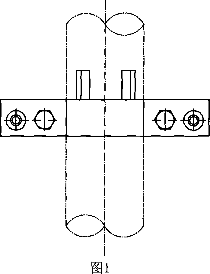
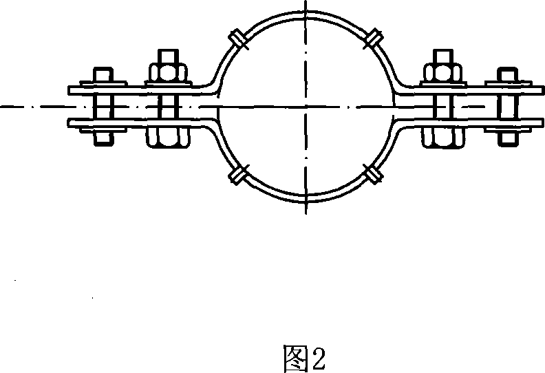
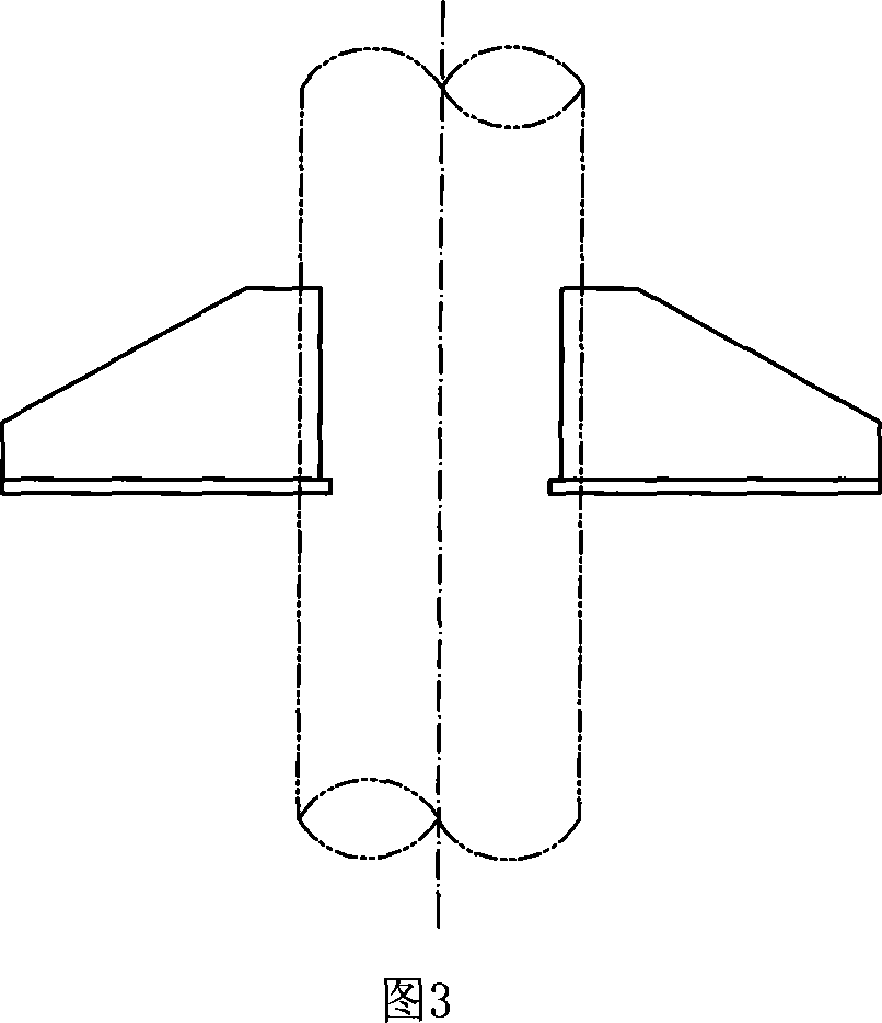
technical field [0001] The invention relates to a support for a pipe or a protective pipe, in particular to a riser support and hanger. Background technique [0002] The existing riser support is as described in the second part P48 of GB / T17116·2-1997 "Pipeline Support and Hanger", as shown in Figure 1. When the temperature of the medium in the pipe is high, the pipe clamp and bolts need to be made of chrome-molybdenum alloy steel. As described in the standard P54 and P64, see Figure 2 and Figure 3, the support welded to the pipe must be the same or compatible with the material of the pipe. If the pipe is made of low-alloy steel or high-alloy steel, the support will cost a lot of money. When the load is large or the temperature is high or both, or the span of the pipe frame increases, the structural consumables will be more. In addition, this structure concentrates the local force on the pipe. When the pipe wall is thin, the pipe rigidity is low, and when the pipe diameter ...

Claims


Application Information

Patent Timeline
Patent Type & Authority Applications(China)
IPC IPC(8): F16L3/00
CPCF16L55/035F16L59/135F16L3/1016
Inventor 王嘉贤王媛媛赵秋菊迟云峰秦楠廉东薇
Owner DALIAN CONSERVATION SCI & TECH CO LTD
Learn More