Method for measuring surface temperature of micro-hotplate

A surface temperature and strength measurement technology, applied in the field of temperature measurement, can solve the problems of inaccurate measurement, small surface area of ​​the micro-hot plate, changing temperature distribution, etc.

Inactive Publication Date: 2007-09-19
JILIN UNIV
View PDF0 Cites 4 Cited by
  • Summary
  • Abstract
  • Description
  • Claims
  • Application Information

AI Technical Summary

Problems solved by technology

The contact temperature measurement methods are mainly thermocouple and thermal resistance. The basic principle is to contact the measuring probe with the object to be measured, and change the temperature of the measuring probe through heat conduction, thereby causing the current or resistance of the measuring probe to change. For the micro-hot plate, since its surface area is equal to or smaller than that of the probe, this temperature measurement method will change the temperature distribution on its surface, resulting in inaccurate measurement
Non-contact temperature measurement is to measure the temperature by focusing the radiant energy emitted by the measured object into the photoelectric device to generate pulse current, but due to the small surface area of ​​the micro-hot plate (generally less than 2×2mm 2 ), and the spot area in this temperature measurement method is relatively too large, so accurate measurement cannot be performed

Method used


Image

  • Method for measuring surface temperature of micro-hotplate
  • Method for measuring surface temperature of micro-hotplate
  • Method for measuring surface temperature of micro-hotplate

Examples


Embodiment 1

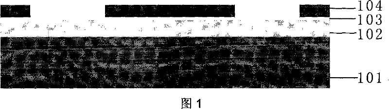
[0029] On the oriented Si substrate 101, SiO with a thickness of 3000 Ȧ was grown by PECVD at 300°C. 2 As the insulating layer 102, and utilizing the magnetron sputtering apparatus to sputter the metal Ti with a thickness of 450 Ȧ as the adhesive layer 103 and the metal Pt with a thickness of 1800 Ȧ as the signal electrode and the heating electrode layer 104 (atmospheric pressure 0.95Pa, temperature 300 ℃, RF power 60W). Then use the photolithography process to cure the photoresist of the electrode pattern shown in Figure 4 on the Si wafer. The area of ​​the micro-hot plate we designed is 5×1.5mm 2 , the width of the heating electrode and the signal electrode is 50 μm, and the distance between the electrodes is 25 μm. Place the coated Si sheet on the position of the target of the magnetron sputtering instrument, and use the impact of Ar ions to remove the parts other than the photoresist on the Si sheet. Pt and Ti are etched away (atmospheric pressure 0.95Pa, temperature 100°C...


PUM


Abstract

The present invention relates to a method for measuring the surface temperature of the tepid board of the sensor based on the intensity of the electromagnetic wave. First, Si radicel sample piece and the tepid board are produced; then, the intensity of the electromagnetic wave with a certain wave length under a certain solid angle of the surface of the Si radicel sample piece and the temperature of the surface of the Si radicel sample piece are measured to obtain the rating curve showing the relation between the intensity of the electromagnetic wave and the surface temperature; the tepid board obtained by cutting the Si radicel sample piece is positioned in a heat and light preventing environment to measure the intensity of the electromagnetic waves having the same wavelength under the same solid angles on the surface of the tepid board, thus, the temperature of the measured area of the surface of the tepid board can be obtained by contrasting the rating curve showing the relation between the intensity of the electromagnetic wave and the surface temperature. The micro-areas having different sizes can be measured by selecting the probe heads with different diameters of the electromagnetic wave detecting instrument, and the measuring of the surface of the tepid board can be performed point by point to obtain the distribution of the temperature of the surface of the tepid board. Thus, an un-contact measuring of the surface of the tepid board can be performed.

Description

technical field [0001] The invention belongs to the technical field of temperature measurement, and in particular relates to a method for measuring the surface temperature of a micro-hot plate of a sensor based on electromagnetic wave intensity. Background technique [0002] Gas sensors have been widely used in fields such as industry, agriculture, electronics and home life. The traditional gas sensor is mainly sintered type, which has high power consumption and poor consistency. The new microstructure gas sensor usually uses Si as the substrate and adopts semiconductor manufacturing technology. Compared with traditional sensors, it has many advantages in terms of consistency, uniformity, and miniaturization, and it is easy to realize sensor integration and low power consumption. Microstructure gas sensors are chemical sensors, and the chemical activity of sensitive materials can be effectively stimulated only when they are heated to a certain temperature. As an important ...

Claims


Application Information

Patent Timeline
IPC IPC(8): G01R29/08G01K11/00
Inventor 张彤漆奇刘奎学刘丽徐宝琨
Owner JILIN UNIV
Why Eureka
Try Eureka