Optimized liquid-phase oxidation
A liquid phase, compound technology, applied in organic oxidation, preparation of organic compounds, organic chemistry, etc., can solve problems such as expensive
- Summary
- Abstract
- Description
- Claims
- Application Information
AI Technical Summary
Problems solved by technology
Method used
Image
Examples
Embodiment 1
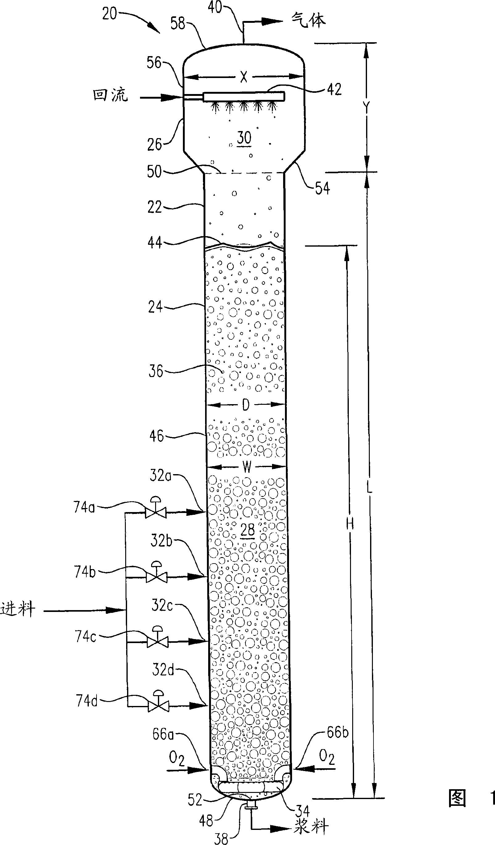
[0347] Example 1 is a calculated example of a bubble column oxidation reactor for the oxidation of para-xylene in the liquid phase of a three-phase reaction medium. The bubble column reactor of Example 1 represents a proven commercial design with a para-xylene feed rate of 7000 kg per hour. Examples 2 to 10 are calculation examples of bubble column oxidation reactors whose operating capacity is 7 times larger than that of the reactor in Example 1. Figure 58 provides a table of various parameters of the modified bubble column oxidation reactor in Examples 1-10.
[0348] Example 1
[0349] This example utilizes a bubble column reaction vessel having a vertical, cylindrical section with an inner diameter equal to 2.44 m. The height of the cylindrical section is 32 m from the lower tangent (TL) to the upper TL of the cylindrical section. The vessel is fitted with 2:1 oval heads on the top and bottom of the cylindrical section. The height from the bottom of the reaction medium ...
Embodiment 2
[0355] In this example, the bubble column reactor was fed with para-xylene at an elevated rate of 49,000 kg per hour—7 times the rate in Example 1. The superficial gas velocity (often considered an important scaling variable for bubble columns) was kept approximately equal to Example 1 by increasing the cross-sectional area of the reaction vessel to about 7 times that in Example 1. The H:W and L:D ratios (often considered important scaling variables for bubble columns) were also kept approximately equal to Example 1.
[0356] The other feed streams were increased by the same ratio as for Example 1 of 7:1. The feed composition was the same as in Example 1, and the same concentrations of water, cobalt, bromine and manganese as in Example 1 were provided within the liquid phase of the reaction medium. The operating pressure of the reaction vessel overhead gas was also 0.52 MPa gauge, and the operating temperature near the middle height of the reaction medium was also about 160...
Embodiment 3
[0362] This example scales up the method of Example 1 using superficial velocities and space-time reaction strengths. This results in poor product quality, in short, because the natural convection mode inherently produces a poor reaction profile vertically.
[0363] In this example, the para-xylene feed rate was also 49000 kg per hour - 7 times the feed rate in Example 1. The superficial gas velocity also remains approximately equal to Example 1, but the L:D and H:W ratios do not remain equal. Instead, STR remained approximately equal to Example 1. This provides approximately equal values for column bottoms pressure and acetic acid decomposition ratio of Example 1. The other feed streams were increased by the same ratio as for Example 1 of 7:1. The feed composition was the same as in Example 1, and the same concentrations of water, cobalt, bromine and manganese as in Example 1 were provided within the liquid phase of the reaction medium. The operating pressure of the rea...
PUM
 Abstract
Description
Claims
Application Information
 - Generate Ideas
- Intellectual Property
- Life Sciences
- Materials
- Tech Scout
- Unparalleled Data Quality
- Higher Quality Content
- 60% Fewer Hallucinations
Browse by: Latest US Patents, China's latest patents, Technical Efficacy Thesaurus, Application Domain, Technology Topic, Popular Technical Reports.
© 2025 PatSnap. All rights reserved.Legal|Privacy policy|Modern Slavery Act Transparency Statement|Sitemap|About US| Contact US: help@patsnap.com


