Electronic ballast

An electronic ballast and circuit technology, applied in the field of electronics, can solve the problems of poor circuit stability and reliability, insufficient output power, etc., and achieve the effects of good stability and reliability, prolonging service life, and improving power output capability.

Inactive Publication Date: 2010-09-01
史俊生
View PDF5 Cites 0 Cited by
  • Summary
  • Abstract
  • Description
  • Claims
  • Application Information

AI Technical Summary

Problems solved by technology

The high-frequency converter composed of the drive circuit of the electronic ballast and the power switches VT2 and VT3 in the high-frequency conversion circuit is a half-bridge inverter. The main problem is that the output power is not large enough, the stability of the whole circuit and less reliable

Method used


Image

  • Electronic ballast
  • Electronic ballast
  • Electronic ballast

Examples


Embodiment Construction

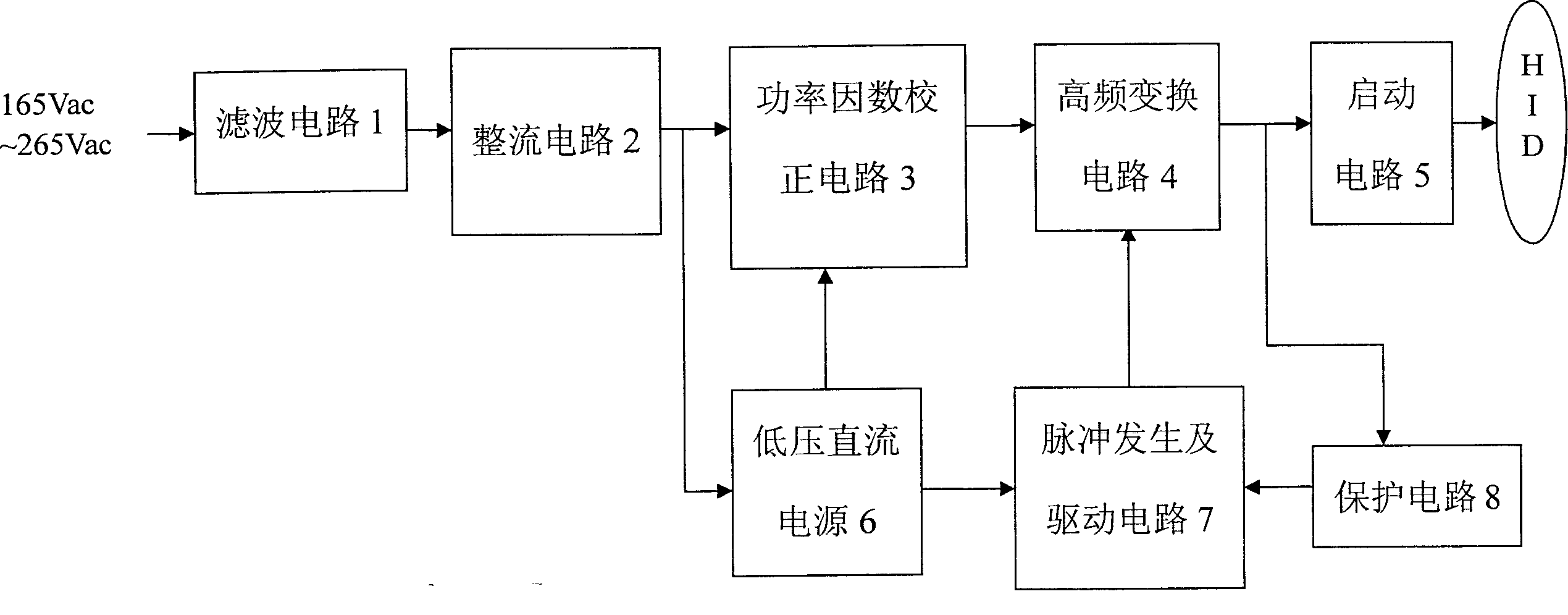
[0017] See figure 1 , the present invention includes a filter circuit 1, a bridge rectifier circuit 2, a power factor correction circuit 3, a high-frequency conversion circuit 4, and a starting circuit 5 connected in sequence, as well as a low-voltage DC power supply 6, a pulse generation and driving circuit 7, and a protection circuit 8. The input end of the low-voltage DC power supply 6 is connected to the output end of the bridge rectifier circuit 2, the output end of the low-voltage DC power supply 6 is connected to the power factor correction circuit 3 and the pulse generation and driving circuit 7, and the high-frequency conversion circuit 4 is connected to the pulse generation and driving circuit 7. A protection circuit 8 is connected between the circuits 7 .

[0018] See figure 2 , The filter circuit 1 is composed of a fuse FU1, a piezoresistor RV, capacitors C1, C2, C23-C25 and high-frequency inductors L1, L2.

[0019] The bridge rectifier circuit 2 is formed by co...


PUM


Abstract

An electronic ballast consists of filtering circuit, bridge rectification circuit, power factor calibration circuit, high frequency transform circuit and start-up circuit being connected in sequence; low voltage DC power supply and pulse generating and driving circuit including all-bridge actuator and four switch accelerators.

Description

technical field [0001] The invention relates to the field of electronics, in particular to a high-power electronic ballast. Background technique [0002] High-intensity discharge lamp (HID lamp) is a new type of energy-saving electric light source with a wide range of uses. Compared with incandescent lamps, it has the advantages of energy saving, small size, good spectrum, high luminous efficiency, and long life. The preferred light source for lighting and the electronic ballasts used with it, especially high-power, high-intensity electronic ballasts, still have problems such as weak power output and poor circuit stability and reliability. Chinese patent ZL01280502.5 discloses an "electronic ballast", including a filter circuit, a bridge rectifier circuit, a power factor correction circuit, a drive circuit and a high-frequency conversion circuit, an output circuit, a 15V voltage regulator circuit, and a pulse width modulator PWM, the AC power first passes through the filter...

Claims


Application Information

Patent Timeline
Patent Type & Authority Patents(China)
IPC IPC(8): H05B41/14H05B41/24
Inventor 陈秀清
Owner 史俊生
Why Eureka
Try Eureka