Material supplying device and method

A technology of supplying device and stirring device, which is applied in the direction of assembling printed circuits, electrical components, circuits, etc. with electrical components, can solve the problems of reduced mechanical strength of metal masks, difficult-to-solder particles supplying workpieces, and paste soldering material falling off, etc. Achieve high-precision and non-fluctuation quantitative discharge, shorten processing time, and simple structure

Inactive Publication Date: 2007-08-08
TAMURA KK
View PDF2 Cites 1 Cited by
  • Summary
  • Abstract
  • Description
  • Claims
  • Application Information

AI Technical Summary

Problems solved by technology

That is, in the screen printing method, the following problems arise: since the opening of the metal mask needs to be miniaturized, the mechanical strength of the metal mask is reduced, or the paste solder becomes difficult to fall off from the opening of...

Method used


Image

  • Material supplying device and method
  • Material supplying device and method
  • Material supplying device and method

Examples


Embodiment Construction

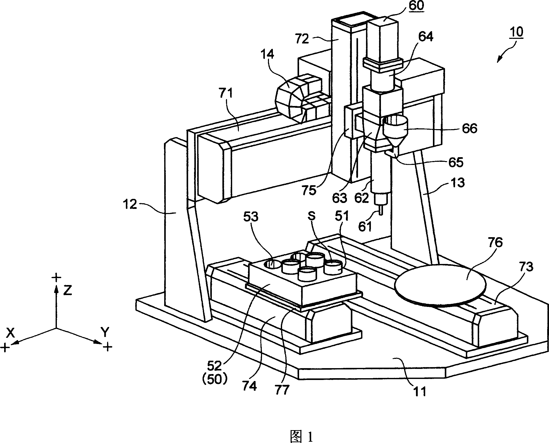
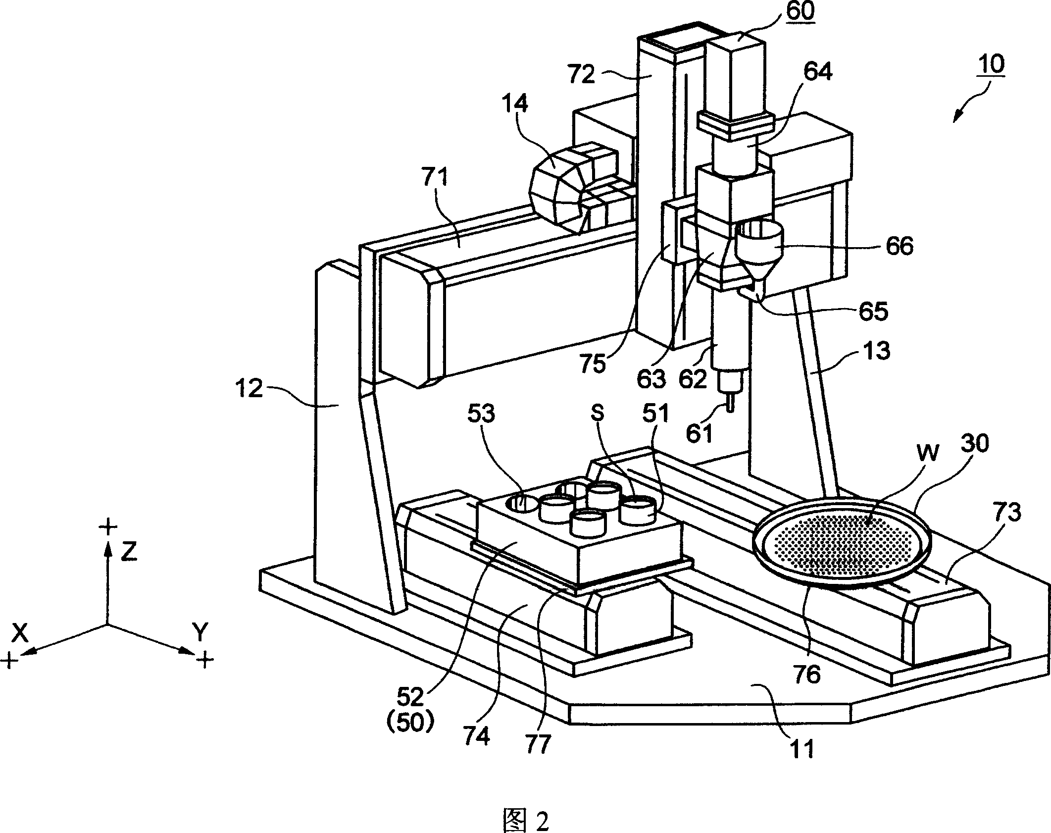
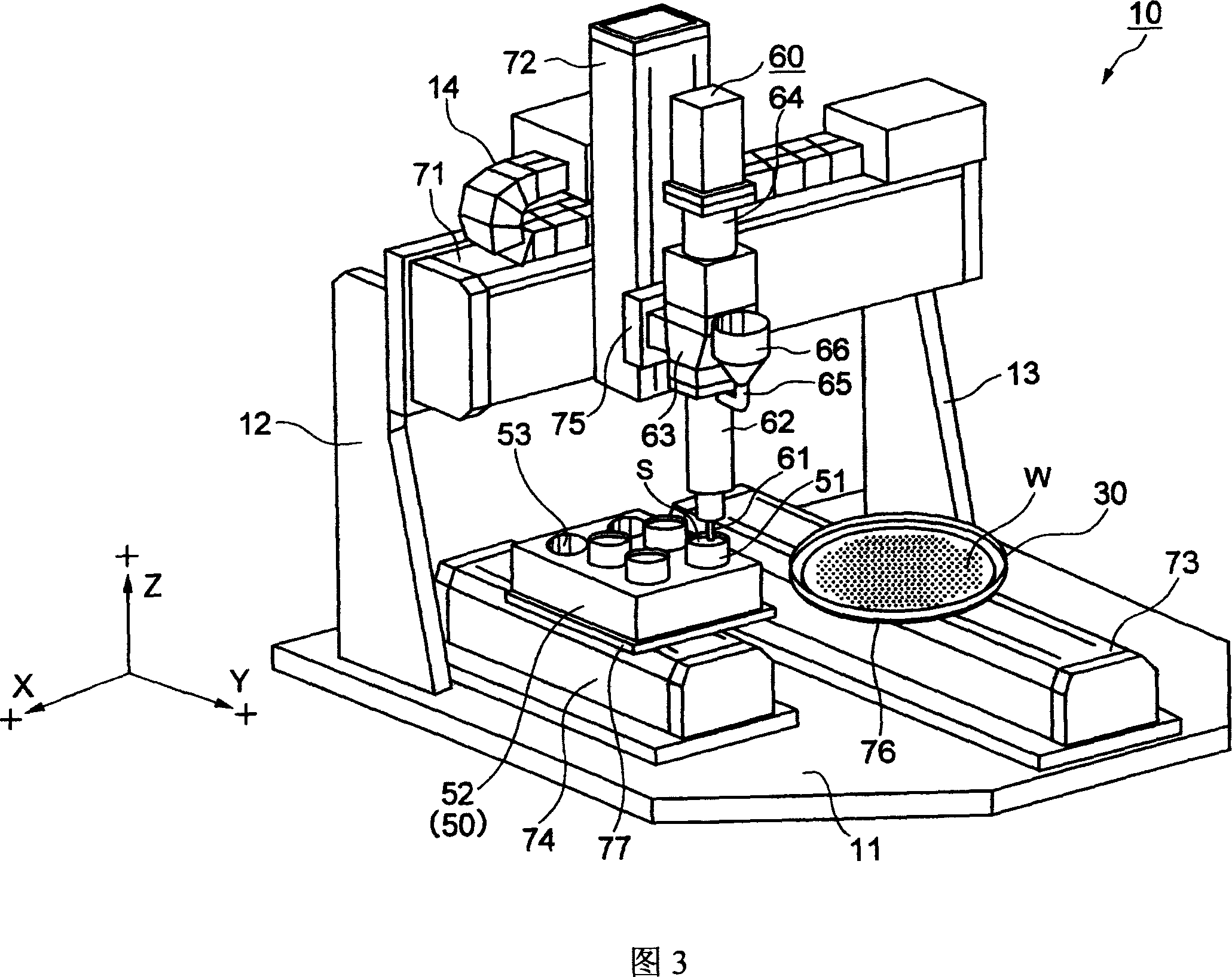
[0042] Embodiments of the present invention will be described below with reference to the drawings.

[0043] 1 to 4 are perspective views showing embodiments of the solder material supply apparatus and method of the present invention, and the steps are performed in the order of FIG. 1 → FIG. 2 → FIG. 3 → FIG. 4 → FIG. 1 . . . Hereinafter, it demonstrates based on these figures. However, since the liquid and solder particles forming the solder material are not shown in the figure, please refer to FIG. 6 and the like.

[0044] In the embodiments of the present invention, solder particles are used as solid particles, liquid having a flux function as liquid, solder material as material, a magnetic stirrer (Magneticus stra) as a stirring device, and a uniaxial eccentric screw pump (hereinafter A dispenser) will be described as an example as a supply device or a pump, and a sub-tank as a storage device.

[0045] First, the structural features, functions, and effects of the solder ...


PUM


Abstract

PROBLEM TO BE SOLVED: To feed a material made of a mixture of solid particles and a liquid to a work as the solid particles are kept dispersed uniformly in the liquid.SOLUTION: A solder material feeder 10 feeds a solder material S made of a mixture of solder particles and a liquid having a flux effect with the solder particles precipitating in the liquid, to a work W using a means including a magnetic stirrer 50 and a dispenser 60. The magnetic stirrer 50 stirs the solder material S in a container 51. The dispenser 60 sucks from the container 51 the solder material S with the solder particles afloat in the liquid as stirred by the magnetic stirrer 50 using a nozzle 61 serving both for suction and delivery, and delivers the solder material S to the work W.

Description

technical field [0001] The present invention relates to a material supply device and method for supplying a material formed from a mixture of liquid and solid particles in which the solid particles settle to a workpiece. More specifically, it relates to a material supply device suitable for forming protruding solder bumps on, for example, semiconductor substrates, interposer substrates, printed wiring boards, etc. to manufacture FC (flip chip) or BGA (ball grid array). Background technique [0002] In the past, the general method of forming solder bumps is to apply paste solder on the pad electrodes of the substrate by using screen printing method or dispensing method (dispensing), and then reflow the paste solder after heating. weld. [0003] On the other hand, Patent Document 1 describes a paste solder made of a mixture of a special solder powder and a fusing agent. The solder powder forms an oxide film on the surface of the solder particles by flowing the solder particl...

Claims


Application Information

Patent Timeline
IPC IPC(8): H01L21/00H01L21/60H05K3/24H05K3/34B23K1/20
CPCH01L24/11H01L2224/11H01L2924/00012
Inventor 白井大小野崎纯一斋藤浩司安藤晴彦
Owner TAMURA KK
Why Eureka
Try Eureka