
Current-limiting reactor of electric power

A current-limiting reactor and electric power technology, applied in the direction of transformer/inductor coil/winding/connection, electrical component structure association, etc., can solve the problems of high cost and increased operating cost, and achieve low cost, simple design and wide market effect of space

Inactive Publication Date: 2010-09-22
INST OF ELECTRICAL ENG CHINESE ACAD OF SCI
View PDF3 Cites 0 Cited by
  • Summary
  • Abstract
  • Description
  • Claims
  • Application Information

AI Technical Summary

Problems solved by technology

[0004] At present, the (high temperature) superconducting current limiter that is being actively developed internationally, although it can achieve better short-circuit current limiting effect, is currently very expensive (such as superconducting materials, low-temperature systems, etc.), and must be maintained by specialized personnel , increase operating costs; and there are still many core technologies such as safety performance, efficiency, etc. that still need to be continuously overcome

Method used


Image

  • Current-limiting reactor of electric power
  • Current-limiting reactor of electric power
  • Current-limiting reactor of electric power

Examples


Embodiment Construction

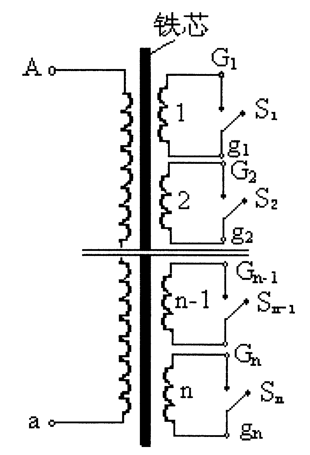
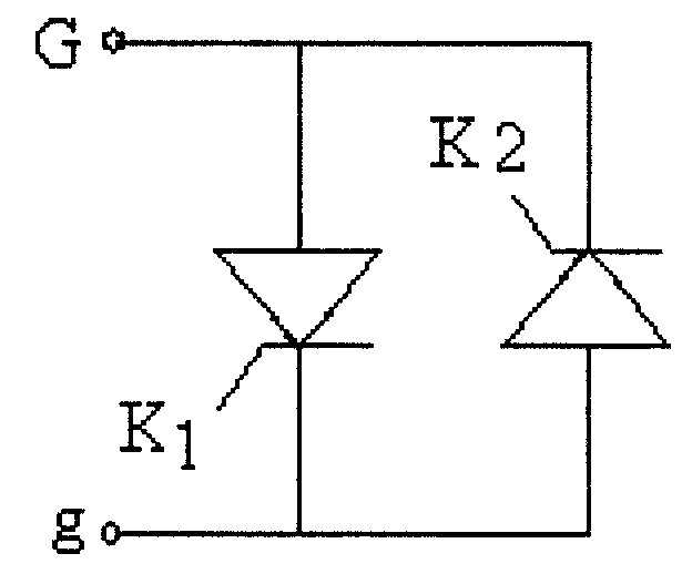
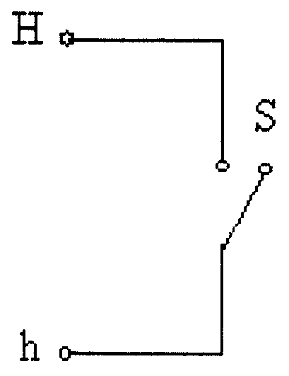
[0017] Such as figure 1 As shown, the present invention includes a power fast switch, an iron core, a winding, a casing (oil tank), a lead wire, a high-voltage terminal, a bushing, and an insulator. Since the main side winding is connected to the power transmission and transformation line, the power transmission and transformation line is generally high voltage, so the main side winding is connected to the power transmission and transformation line terminal A, a, and the power transmission and transformation line. The terminal A, a includes bushing, Insulated terminals, leads. n secondary windings 1, 2,...n-1, n are wound on the iron core, and the primary winding is wound outside the secondary winding. Each secondary winding has 2 taps, such as G 1 , g 1 , can be pulled out of the winding, respectively connected to the corresponding fast power switch, such as S1, n secondary windings 1, 2, ... n-1, n are respectively connected to the corresponding fast power switch S1, S2, ...


PUM


Abstract

The invention relates to power limit flow reactor, which is characterized by the following: main edge lines pass through transducer circuit connection terminal; n side coil sets one to n-1 are coiled on iron core and main set is on side coil set connected to the rapid switch S1 to Sn; the rapid power switches adopt transistor tube switch or air rapid switch with one main edge coil set according to different voltages and shortcut current degree.

Description

technical field [0001] The invention relates to a power current limiting reactor. Background technique [0002] As the capacity of the power grid in the power system increases day by day, the short-circuit current of the system is greatly enhanced, and the short-circuit fault has become one of the most prominent problems that damage the equipment in the power system and endanger the safe operation of the power system. At present, the common method used to limit the short-circuit current of the system is to increase the reactance in the system, that is, to use high-impedance transformers, series reactors in the system and other technical means to achieve the purpose of current limitation. Recently, many countries have researched and developed a new technology of superconducting current limiter to limit short-circuit current. [0003] If high-impedance transformers and reactors are used, the input cost of the power system will be greatly increased, and the reactive power loss...

Claims


Application Information

Patent Timeline
Patent Type & Authority Patents(China)
IPC IPC(8): H01F27/28H01F27/40
Inventor 肖立业王银顺赵彩宏惠东林良真
Owner INST OF ELECTRICAL ENG CHINESE ACAD OF SCI
Learn More