Ruled surface impeller tool path planning and processing method
A processing method and tool trajectory technology, applied in the direction of instruments, computer control, simulators, etc., can solve the problems of complex operation, low processing and cutting efficiency, and no calculation method for tool center point or tool tip point
- Summary
- Abstract
- Description
- Claims
- Application Information
AI Technical Summary
Problems solved by technology
Method used
Image
Examples
specific Embodiment approach 1
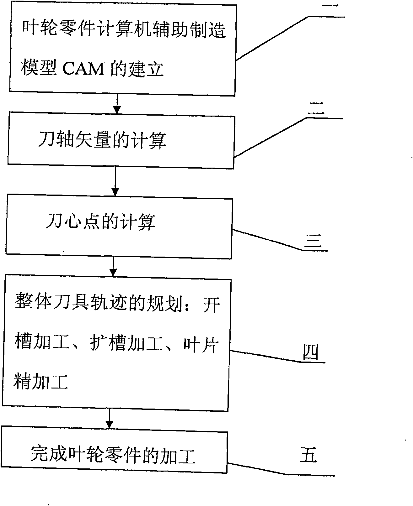
[0025] Specific implementation mode one: as figure 1 As shown, the tool trajectory planning and processing method of the ruled surface impeller described in this embodiment is realized according to the following steps:
[0026] Step 1. Establishment of the computer-aided manufacturing model CAM of the impeller parts: read the ordered value points (trajectory data) on the curve of the three-dimensional design drawing of the impeller by the CAM software, and use the approximation algorithm to process the read ordered value points Approximate fitting of various curves on the impeller to obtain the CAM model of the impeller parts;
[0027] In engineering, the shape of the impeller is generally designed according to the aerodynamic or fluid dynamic performance index, or measured by a three-coordinate measuring instrument. Either way, the data points generally given on the drawing describe the surface of the impeller blade. For an impeller with a ruled surface, the data points usu...
specific Embodiment approach 2
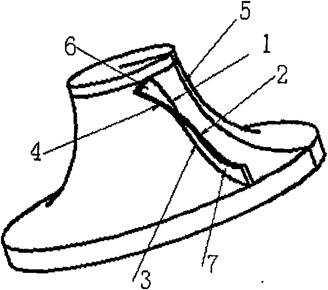
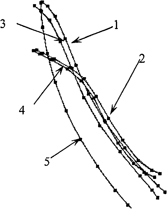
[0052] Specific implementation mode two: as figure 2 and image 3 As shown, the approximation algorithm in step 1 of this embodiment is to use the least squares method to perform the upper curve of the ruled surface impeller (blade back shaft disk curve 1, blade back cover disk curve 2, blade pot shaft disk curve 3, blade For the approximation of the pot cover curve 4 and the hub section line 5), the specific steps are as follows:
[0053] Step a, the ordered value point sequence P on the curve of the three-dimensional design diagram of the impeller to be read i (i=0,...,m) is constructed as a B-spline curve:
[0054] r ( u ) = Σ i = 0 n V i · N i , k ( u ...
specific Embodiment approach 3
[0064] Specific implementation mode three: as Figure 4 and Figure 6 As shown, the specific steps of calculating the position of the knife center point in step 3 of this embodiment are as follows:
[0065] Step i, first discretize the offset curved surface 9 of the impeller hub surface 8 into triangular pieces, and calculate the position of the intersection point by applying the triangle piece and the space directed line segment to find the intersection point, and the position of the intersection point is the position of the knife center point;
[0066] The discretization of the offset curved surface of the impeller hub surface into triangular pieces is carried out as follows:
[0067] One), according to the equal parameter method, calculate the derivative vector n3 of each point on the hub section line;
[0068] 2) The cross product of the guide vector and the unit normal vector of the plane where the hub section line is located obtains the normal vector n4 of the section ...
PUM
 Abstract
Description
Claims
Application Information
 - R&D
- Intellectual Property
- Life Sciences
- Materials
- Tech Scout
- Unparalleled Data Quality
- Higher Quality Content
- 60% Fewer Hallucinations
Browse by: Latest US Patents, China's latest patents, Technical Efficacy Thesaurus, Application Domain, Technology Topic, Popular Technical Reports.
© 2025 PatSnap. All rights reserved.Legal|Privacy policy|Modern Slavery Act Transparency Statement|Sitemap|About US| Contact US: help@patsnap.com


