Fischer-Tropsch synthesis method

A technology for Fischer-Tropsch synthesis and coal-to-synthesis gas, which is applied in the recovery of liquid hydrocarbon mixtures, petroleum industry, etc., can solve the problems of increasing the tail gas emission of the second-stage device, reducing the process economy, reducing the conversion rate, etc., and achieves improvement. The effect of distribution, improved utilization, and improved conversion rate

Active Publication Date: 2009-12-30
CHNA ENERGY INVESTMENT CORP LTD +1
View PDF5 Cites 6 Cited by
  • Summary
  • Abstract
  • Description
  • Claims
  • Application Information

AI Technical Summary

Problems solved by technology

The process adopts two-stage Fischer-Tropsch synthesis, which can reduce CH by reducing the conversion rate of single-stage CO. 4 production rate, but the tail gas of the first-stage unit directly enters the second-stage Fischer-Tropsch synthesis unit, and the CO generated by the first-stage Fischer-Tropsch synthesis unit 2 Inert gases such as methane and methane will accumulate in the second-stage device, which leads to the maintenance of operation by increasing the tail gas discharge of the second-stage device to reduce the concentration of inert gas in the circulating gas of the second-stage device in actual operation, reducing the overall economy of process

Method used


Image

  • Fischer-Tropsch synthesis method

Examples


Embodiment 1

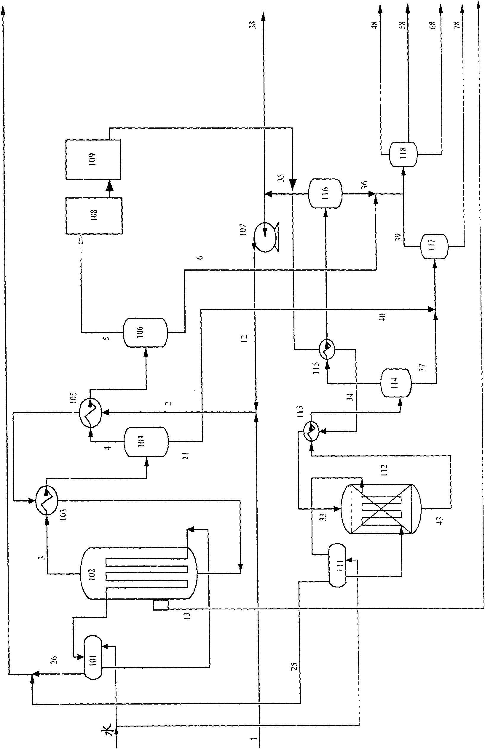
[0031] This embodiment adopts figure 1 In the process flow shown, the fresh raw material gas is coal gasified, then purified and water-gas shifted to obtain H 2 The synthesis gas with a / CO volume ratio of 1.5, the specific composition is shown in Table 1.

[0032] Table 1 Composition of raw materials for coal-based syngas

[0033] Composition, v%

[0034] The weight composition of the iron-based catalyst used in the primary reactor is 100Fe:5Cu:5K 2 O: 25SiO 2 . Its preparation method is to first mix ferric nitrate and copper nitrate solution in proportion to form a mixed solution, and then add Na 2 CO 3 The solution was precipitated, then filtered and washed free of alkali; the filter cake was beaten and excess K 2 SiO 3 , and join the HNO 3 Wash off excess potassium ions, wash and filter, beat the filter cake and spray dry to obtain catalyst particles with a particle size range of 60-90 microns. After the catalyst is reduced, it can be used as a qualified ...

Embodiment 2

[0047] This embodiment adopts figure 1 In the process flow shown, the fresh raw material gas is coal gasified, then purified and water-gas shifted to obtain H 2 The synthesis gas with a / CO volume ratio of 1.3, the specific composition is shown in Table 5.

[0048] Table 5 Composition of raw materials for coal-based syngas

[0049] Composition, weight %

[0050] The iron-based and cobalt-based catalysts used in the primary and secondary reactors are the same as in Example 1.

[0051] Fresh raw material gas and recycle gas are mixed according to the ratio of 2, and then reacted under the process conditions listed in Table 6. About 75% of CO+H 2 Converted in the first stage reactor. The tail gas of the primary reactor is deCOated by potassium carbonate 2 After treatment, the C1-C4 hydrocarbons are converted by the methane autothermal oxidation device, and the treated tail gas enters the second-stage reactor, and reacts under the process conditions listed in Table 6...


PUM

PropertyMeasurementUnit
particle sizeaaaaaaaaaa

Abstract

This invention relates to a synthesis method of fischer-tropsch. Its preparation includes (1) Coal-made synthesis gas material enters into the first fischer-tropsch synthesis reactor to contact and react with iron base catalyst, (2) After eliminating CO2 from surplus end gas, segregating the first grade reaction product for entering C1-C4 alkanes transformation equipment to produce CO and H2, and then let the end gas after transformation enter the second fischer-tropsch synthesis reactivator to contact and react with cobalt base accelerant. (3) Segregating the second reaction product and evacuating part of gas, and then let the surplus end gas return to the first fischer-tropsch reactor for recycling. This method can adjust the reaction extent between first and second grade reaction to control the aimed product structure flexibly and meet the demand of the market.

Description

technical field [0001] The invention relates to a Fischer-Tropsch synthesis method, more specifically, a two-stage Fischer-Tropsch synthesis method using coal-based synthesis gas as a raw material. Background technique [0002] As the price of oil continues to rise in recent years, people pay more and more attention to the development of technologies to produce alternative oil products. Using coal, natural gas or other biomass as raw materials and using Fischer-Tropsch synthesis as the core technology to produce high-quality, environmentally friendly oil products has become a current research hotspot. my country's energy structure is characterized by more coal and less oil. The technology of producing oil products from coal is one of my country's strategies to deal with oil shortages. It can be seen that the development of coal-to-oil technology is urgent and realistic in my country. [0003] So far, the Fischer-Tropsch synthesis process of iron-based and cobalt-based catal...

Claims


Application Information

Patent Timeline
Patent Type & Authority Patents(China)
IPC IPC(8): C10G5/00
Inventor 石玉林任相坤门卓武林泉王鹏袁明
Owner CHNA ENERGY INVESTMENT CORP LTD
Why Eureka
Try Eureka