
Controller for hydraulic construction machine

A technology for hydraulic construction machinery and control devices, applied in engine control, fluid pressure actuation device, electrical control, etc., can solve the problems of discontinuous engine rotation fluctuations, undesired mode switching by the operator, and incongruity, etc. The effect of reducing performance degradation, improving fuel consumption, and improving operability

Active Publication Date: 2009-10-28
NIHON KENKI CO LTD
View PDF4 Cites 1 Cited by
  • Summary
  • Abstract
  • Description
  • Claims
  • Application Information

AI Technical Summary

Problems solved by technology

In the system disclosed in Japanese Patent Application Laid-Open No. 62-160331, the maximum discharge flow rate is ensured only in the low-pressure pump discharge pressure range as described above, and it is not effective in the area where the pump load frequency is high (the intermediate pump discharge pressure range).
[0011] In addition, if various detection components are provided and a mode suitable for the current working state is automatically selected, not only the mode switching that the operator does not expect will occur, but also the fluctuation of the engine rotation or the fluctuation of the pump discharge flow will occur discontinuously, and it will feel uncomfortable. A sense of coordination, and many detection components need to be installed, which is also disadvantageous in terms of cost

Method used


Image

  • Controller for hydraulic construction machine
  • Controller for hydraulic construction machine
  • Controller for hydraulic construction machine

Examples


Embodiment Construction

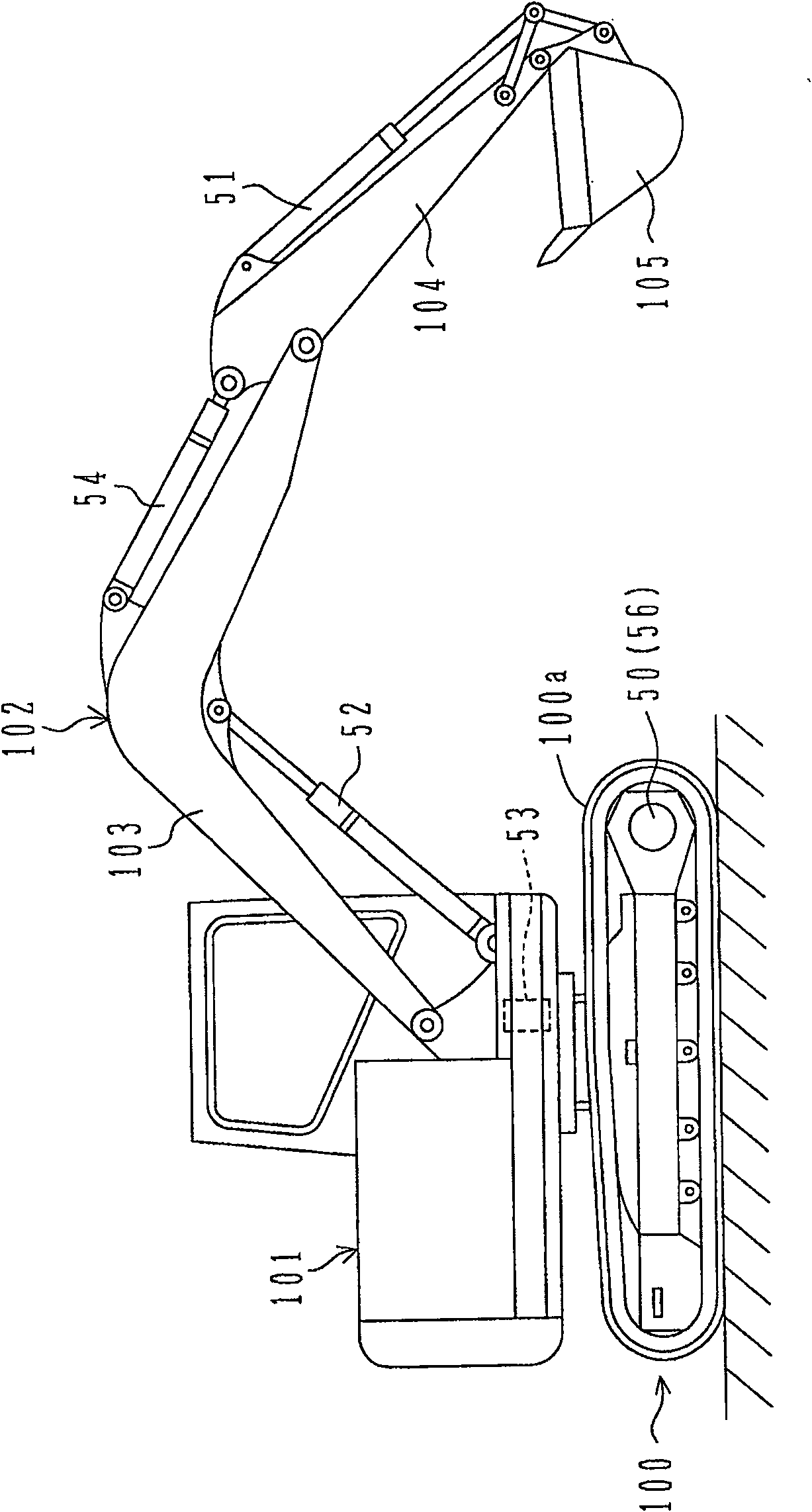
[0083] Embodiments of the present invention will be described below using the drawings. The following embodiments are cases in which the present invention is applied to a prime mover of a hydraulic shovel and a control device for a hydraulic pump.

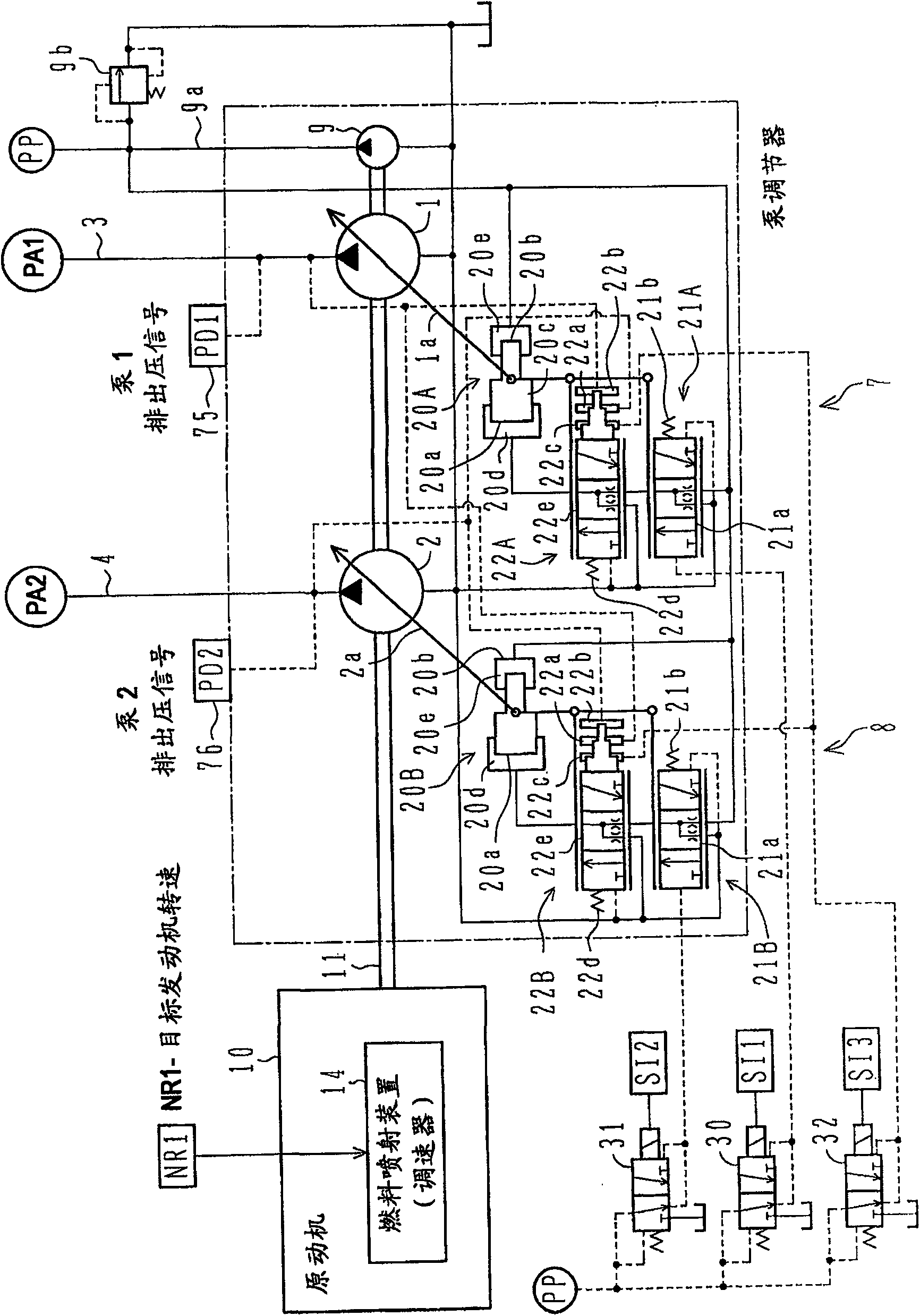
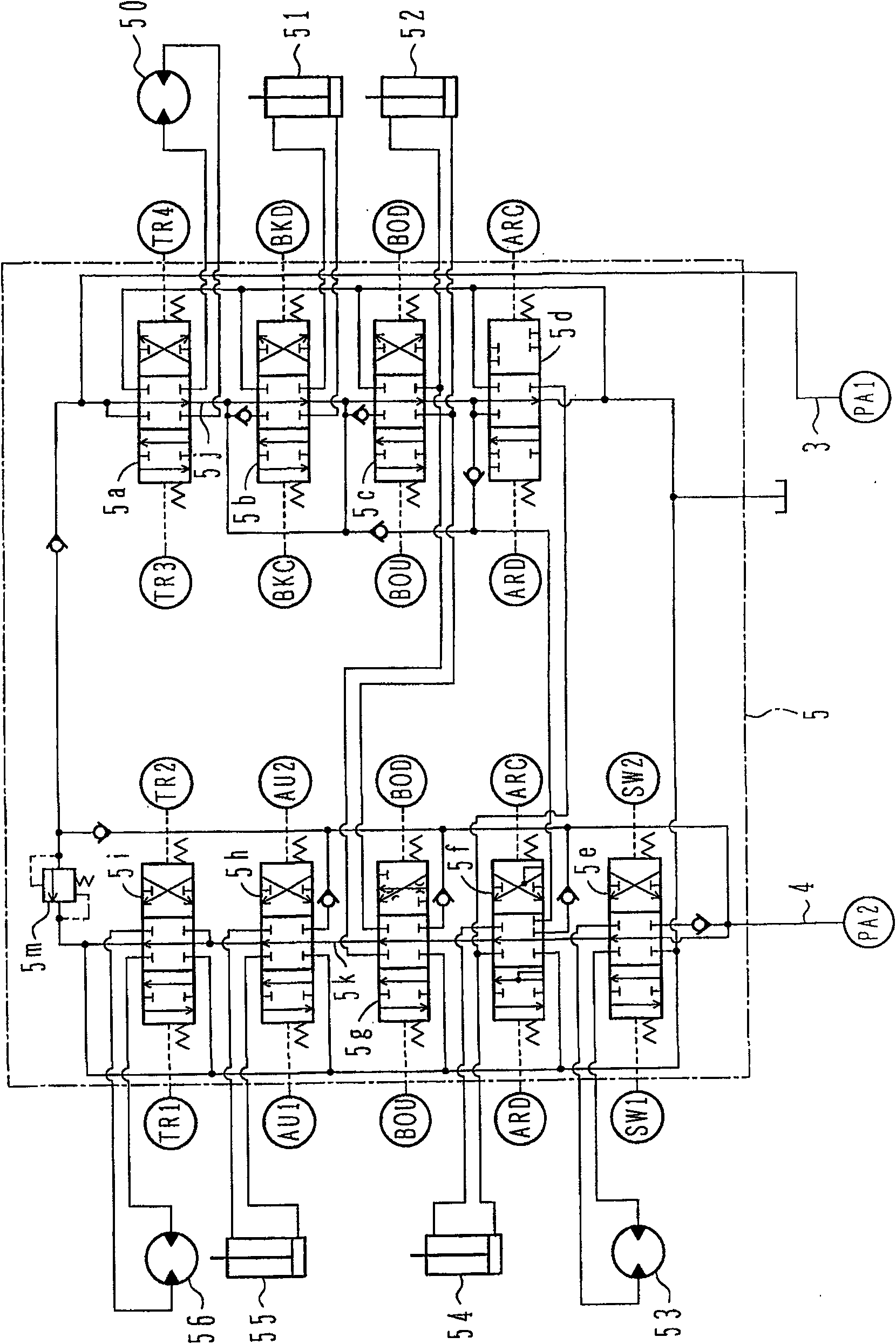
[0084] exist figure 1 Among them, 1 and 2 are, for example, swash plate type variable capacity hydraulic pumps, and the discharge paths 3 and 4 of the hydraulic pumps 1 and 2 are connected to figure 2 The shown valve device 5 sends hydraulic oil to a plurality of actuators 50 to 56 via the valve device 5 and drives these actuators.

[0085] 9 is a pilot pump of fixed capacity type, and the pilot relief valve 9b which maintains the discharge pressure of the pilot pump 9 to a constant pressure is connected to the discharge path 9a of the pilot pump 9.

[0086] The hydraulic pumps 1 and 2 and the pilot pump 9 are connected to the output shaft 11 of the prime mover 10 and are rotationally driven by the prime mover 10 .

[0087] The...


PUM


Abstract

The mode selection part (700e) is turned on when the mode selection instruction selects the economic mode, and outputs the engine speed correction value ΔN0 (ΔN1=ΔN0) calculated by the engine speed correction value calculation part (700d), and the subtraction part (700f) calculates the engine speed correction value ΔN0 from the rated value. Corrected engine speed ΔN1 is subtracted from target speed Nmax to obtain target engine speed NR2. A calculation unit (700d) calculates an engine rotation speed correction value ΔN0 corresponding to the pump discharge pressure average value Pm. In the memory table, the relationship between Pm and ΔN0 is set as follows: when Pm is below PA near the intermediate pressure, ΔN0 is 0, and when Pm is higher than PA, ΔN0 increases with the increase of Pm. Accordingly, through mode selection, the prime mover speed can be reduced to improve fuel consumption, and at the same time, in the necessary load area, the performance degradation caused by the reduction of pump discharge flow can be reduced, and the prime mover speed or pump discharge flow will not be discontinuous. Variety.

Description

technical field [0001] The present invention relates to a control device for a hydraulic construction machine, and more particularly to a control device for a hydraulic construction machine such as a hydraulic excavator that drives a hydraulic actuator to perform necessary work and has a mode selection member through hydraulic oil, the hydraulic oil being driven from The hydraulic pump driven by the prime mover (engine) discharges, and the mode selection means selects a control mode related to the prime mover to control the engine speed. Background technique [0002] In hydraulic construction machines such as hydraulic shovels, generally, a diesel engine is used as a prime mover, at least one variable displacement hydraulic pump is driven by this engine, and a plurality of hydraulic actuators are driven by hydraulic oil discharged from the hydraulic pump. , to perform the necessary work. This diesel engine has an input member such as a throttle plate for commanding a target...

Claims


Application Information

Patent Timeline
Patent Type & Authority Patents(China)
IPC IPC(8): F02D29/04F02D29/00E02F9/22F15B11/00
CPCE02F9/2235E02F9/2292F02D2200/604E02F9/2296F15B2211/20553F02B3/06F02D31/007E02F9/2242F15B21/14F15B2211/20576F02D41/021F15B11/17F02D29/02F15B2211/88E02F9/2246F15B21/087F02D29/04F02D29/00E02F9/22F15B11/00
Inventor 有贺修荣中村和则石川广二
Owner NIHON KENKI CO LTD
Learn More