
CAN bus conversion module

A CAN bus and conversion module technology, applied in the field of CAN bus conversion modules, can solve the problems of not meeting the signal exchange requirements and large amount of information exchange

Active Publication Date: 2009-08-26
CHERY AUTOMOBILE CO LTD
View PDF4 Cites 0 Cited by
  • Summary
  • Abstract
  • Description
  • Claims
  • Application Information

AI Technical Summary

Problems solved by technology

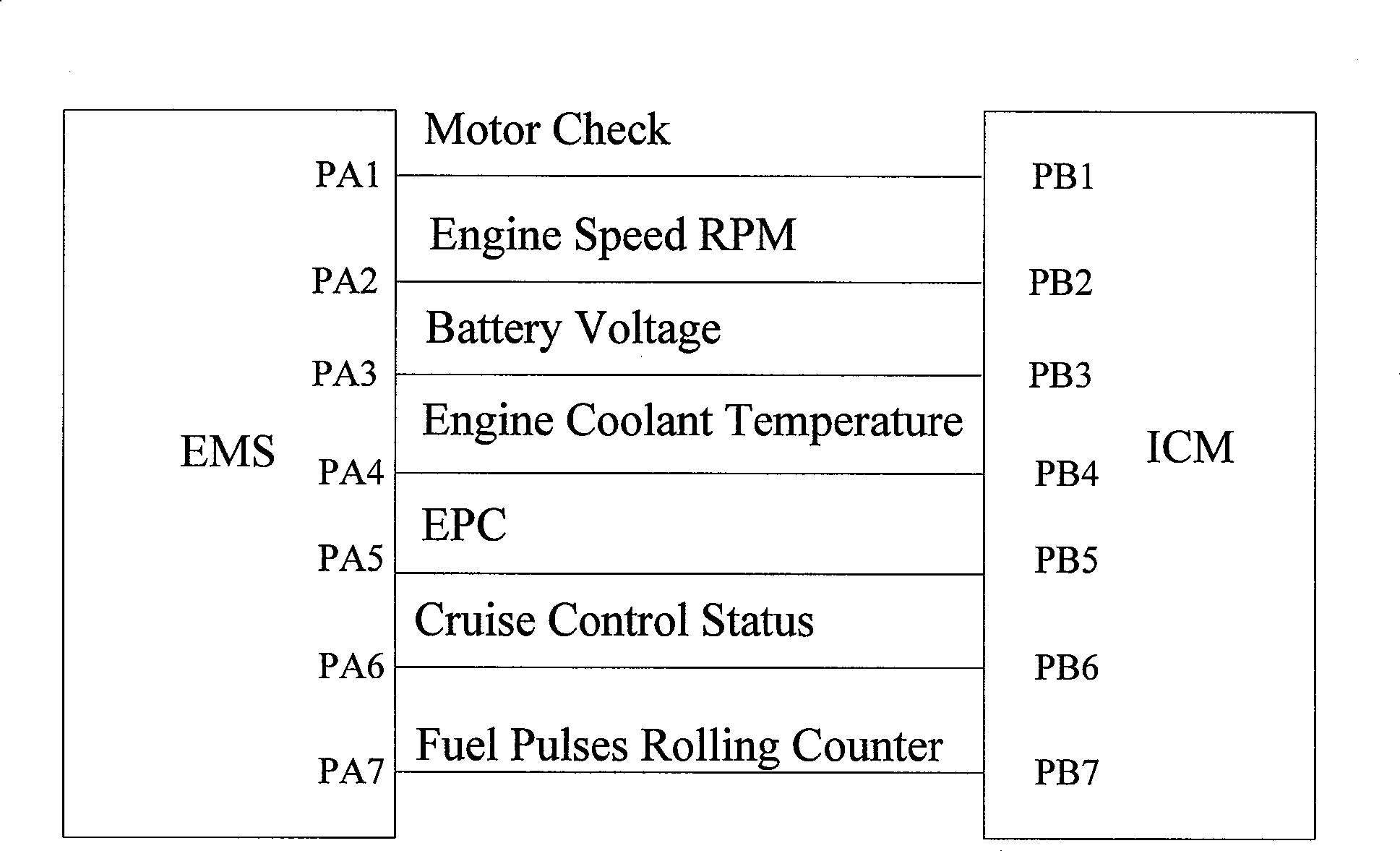
However, due to the huge amount of information exchange between the automatic transmission and EMS, the traditional wiring harness connection can no longer meet the signal exchange requirements, so the automatic transmission and EFI must use CAN communication

Method used


Image

  • CAN bus conversion module
  • CAN bus conversion module
  • CAN bus conversion module

Examples


Embodiment Construction

[0019] The present application will be further described in conjunction with the accompanying drawings.

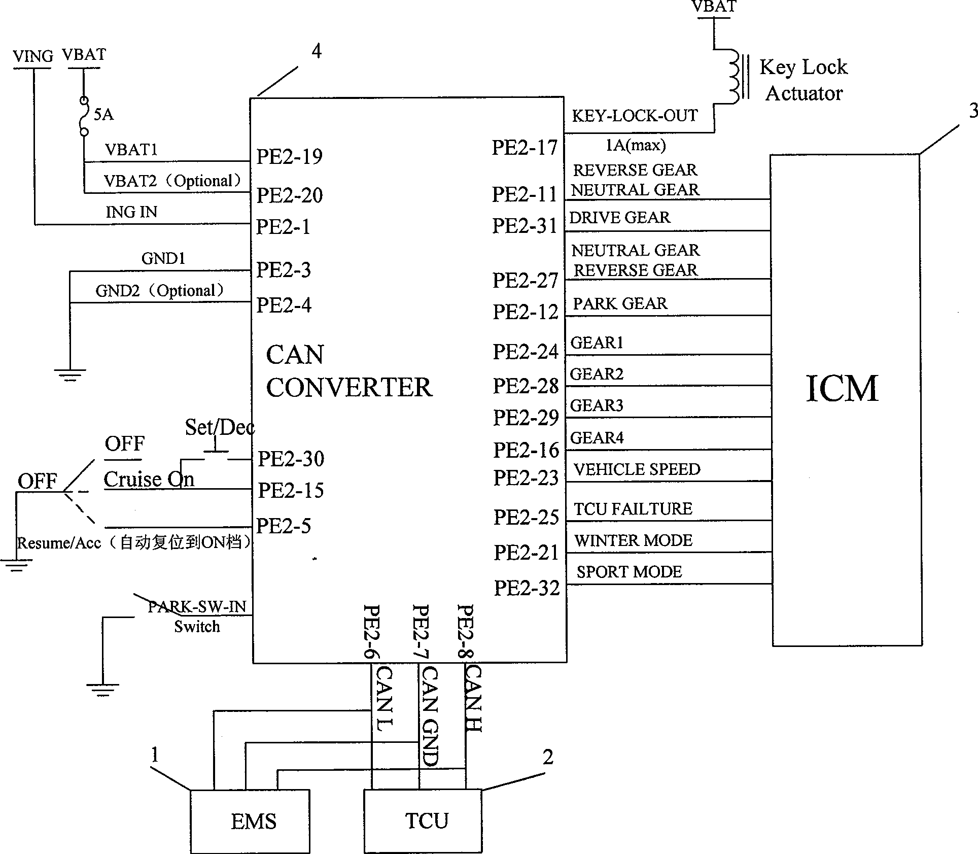
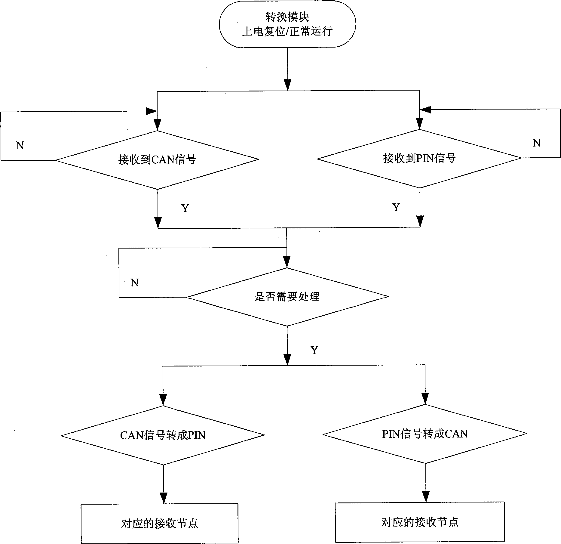
[0020] like figure 2 As shown, the engine control system (electric injection system) EMS1 is connected to CAN, the automatic transmission TCU2 is also connected to CAN, and the instrument ICM3 is not connected to CAN. In order to realize the communication between these three controllers, a CAN conversion is added. Module 4, its function is to convert the CAN signal sent by the EFI system 1 or the automatic transmission 2 into a PIN signal that can be recognized by the meter 3 and send it to the meter for display; on the other hand, it can receive the PIN signal sent by the meter 3, Convert it into a CAN signal and send it to the EFI system 1 or the automatic transmission 2 to realize the mutual conversion between the traditional PIN signal and the bus signal. image 3 The working flow chart of the conversion module is shown, and a simple software program is listed below ...


PUM


Abstract

The present invention discloses a CAN bus conversion module, including a CAN interface and a PIN interface, which can carry out the mutual conversion between CAN signal and PIN signal. The conversion module includes a general system controller for controlling the input and output of various signals such as PIN or frequency or PWM and simultaneously being used as a CAN controller; a diagnosis controller for recording the fault diagnosis of the controller of other nodes or the node of the whole bus and supporting the work of a diagnosing machine; a CAN transceiver, which is a CAN physical layer hardware support for mutual conversion between the CAN signal and telecommunication signal; a CAN controller in which a chip microcomputer can control the data sending and receiving by the program setup of a programmable chip; and a memory. The diagnosis controller also has a diagnosing function. The conversion module can solve the match of the communication between vehicles with CAN equipment and vehicles without CAN equipment, thus constructing a local CAN sub-system matched with the whole vehicle power system in a non-CAN vehicle system.

Description

technical field [0001] The invention relates to signal conversion, in particular to a CAN bus conversion module. Background technique [0002] In recent years, with the development of chip manufacturing technology and the gradual enhancement of controller functions, vehicle controllers for various purposes have been widely used in automobiles. The use of these microcomputers in automobiles has greatly improved the safety of automobiles. Performance and comfort, showing the progress of human civilization and technology. The increasing number of electrical controllers has led to a sharp increase in the amount of wire harnesses used for signal exchange, and the negative impact is to increase the weight of the vehicle and potential safety hazards. At this time, vehicle bus technology came into being. The application of the bus enhances the communication capability between the controllers and eliminates the disadvantages of wiring harness communication. Therefore, the vehicle b...

Claims


Application Information

Patent Timeline
Patent Type & Authority Patents(China)
IPC IPC(8): G06F13/40G05B19/418B60R16/02
CPCG07C5/08Y02P90/02
Inventor 张邵进
Owner CHERY AUTOMOBILE CO LTD
Learn More