
Micro electromechanic safe coded lock encoded method for processing gear wheel, and process unit

A technology for encoding gears and processing devices, which is applied in transportation and packaging, wheels, metal extrusion dies, etc., can solve the problems of long process cycle, large investment in LIGA technology equipment, and difficulty in reducing component size, achieving short process cycle, Excellent structural strength and reduced component size

Inactive Publication Date: 2008-05-14
INST OF METAL RESEARCH - CHINESE ACAD OF SCI
View PDF3 Cites 0 Cited by
  • Summary
  • Abstract
  • Description
  • Claims
  • Application Information

AI Technical Summary

Problems solved by technology

[0014] In order to overcome various deficiencies in the prior art, such as large investment in LIGA technical equipment; long process cycle; difficulty in reducing component size; and certain difficulties in assembling LIGA parts into components / complete machines, one of the purposes of the present invention is to provide a Viscous flow behavior of bulk amorphous alloys in the supercooled temperature region, forming anti-interference micro-electromechanical security combination lock coding gear processing method by micro-extrusion

Method used


Image

  • Micro electromechanic safe coded lock encoded method for processing gear wheel, and process unit
  • Micro electromechanic safe coded lock encoded method for processing gear wheel, and process unit
  • Micro electromechanic safe coded lock encoded method for processing gear wheel, and process unit

Examples


Embodiment 1

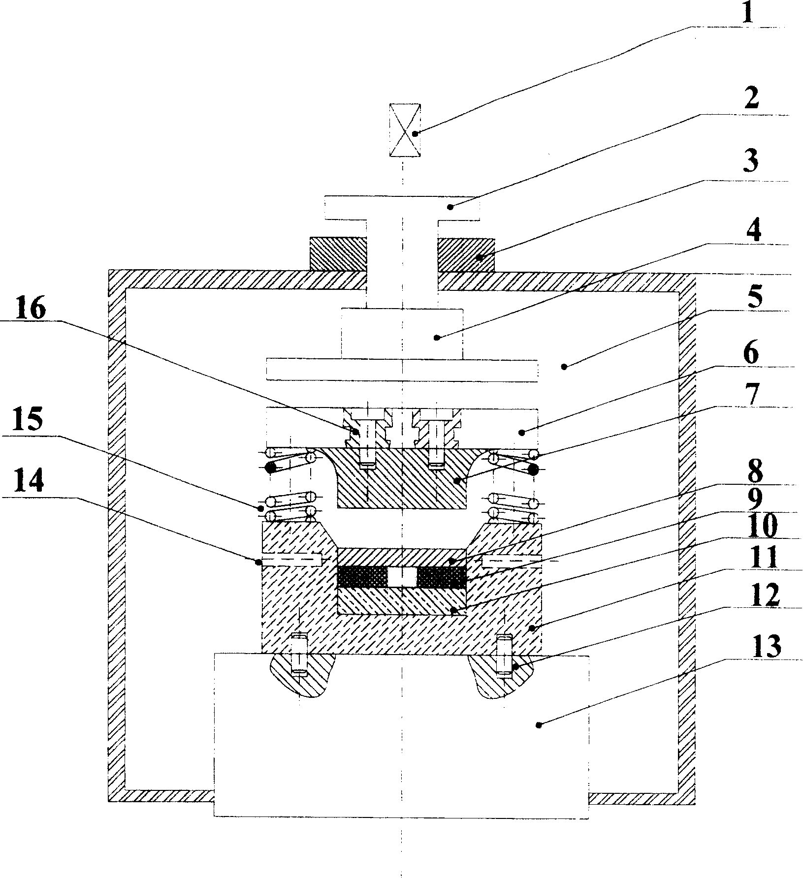
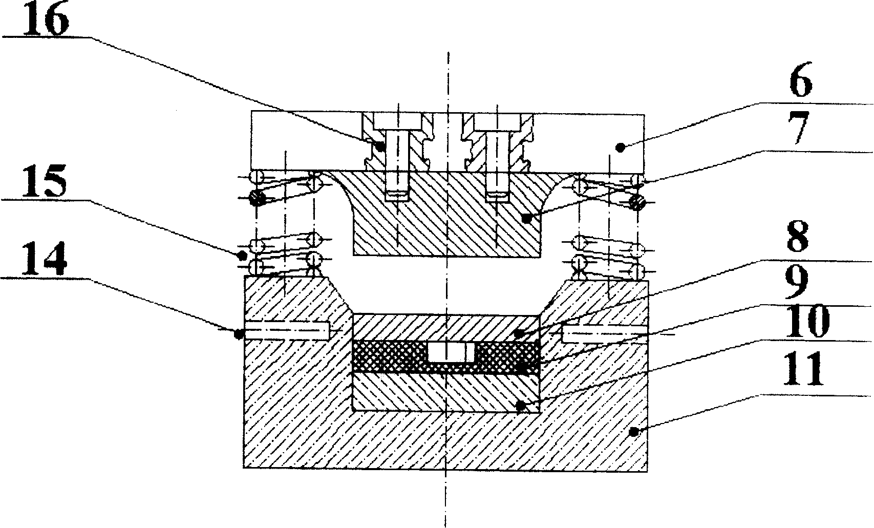
[0045] Combine below figure 2 with Figure 3-1 , 3-2 This embodiment will be specifically described.

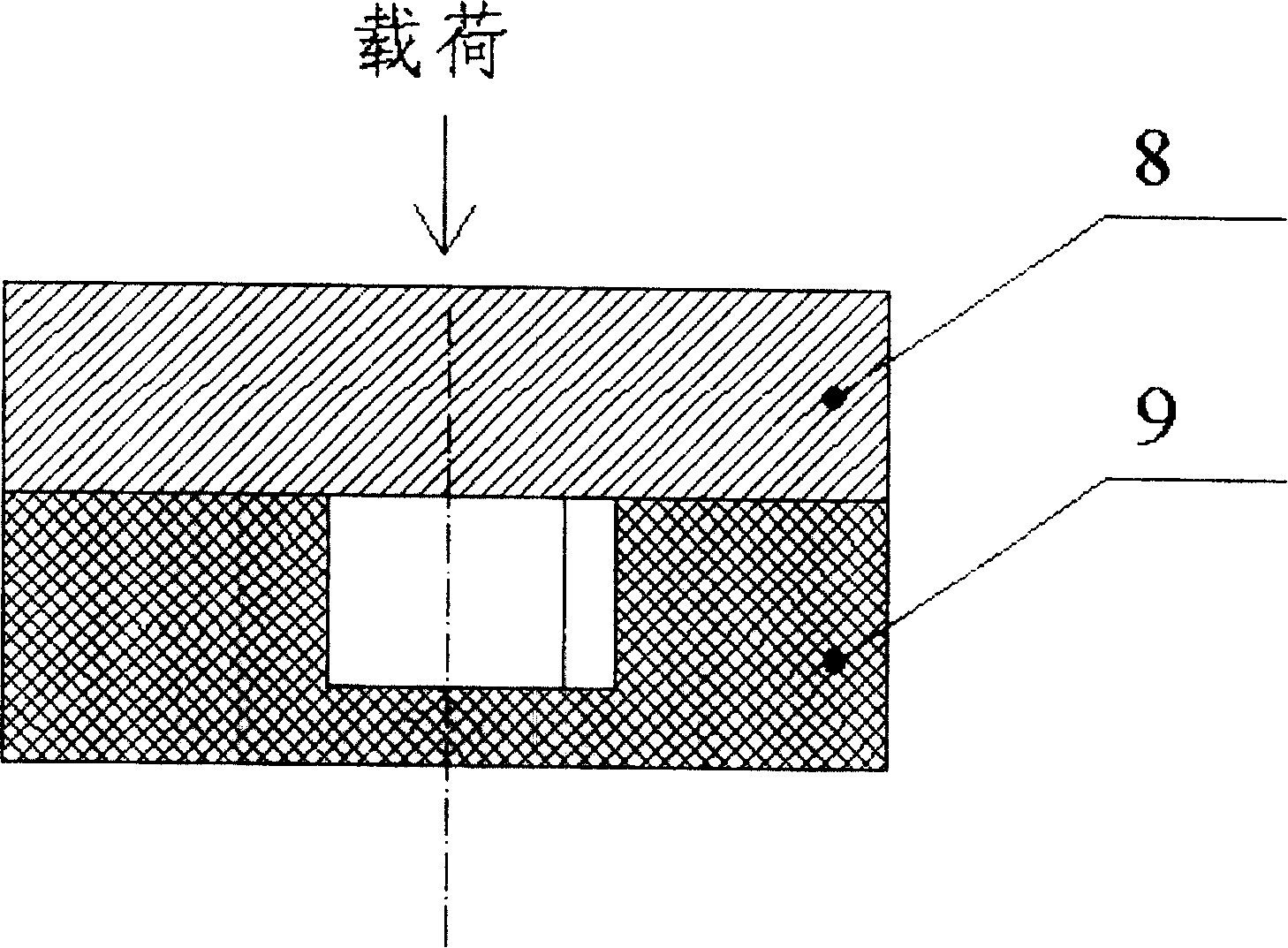
[0046] The processing device of the present invention consists of a micro linear motor 1, an upper pressing head 2, a limit sleeve 3, a magnetostrictive actuator 4, a gas-protected non-contact heating furnace 5, a punch base 6, a punch 7, a blank 8, Die 9, cushion block 10, mold base 11, positioning pin 12, lower pressure head 13, temperature measuring blind hole 14, return spring 15 and connecting screw 16, wherein: miniature linear motor 1 is connected with the top of upper pressure head 2, Used to apply a larger output displacement. The neck of the upper pressure head 2 is provided with a limit sleeve 3 to avoid damage to the magnetostrictive actuator 4 due to an excessive stroke. The lower end of the upper pressing head 2 is installed in the gas shielded non-contact heating furnace 5 . The non-contact heating furnace 5 uses a fan to evenly transmit the heat generate...

Embodiment 2

[0056] Combine below figure 2 and Fig. 4-1, 4-2 specifically illustrate this embodiment. The processing device differs from that of Embodiment 1 in that the mold 9 is a double-layer multi-tooth coded gear concave mold.

[0057] The processing technology includes the following steps:

[0058] 1. According to the specific outline size of the coding gear, choose a large piece of Mg with a diameter of 2mm and a thickness of 1.6mm 65 Cu 25 Y 10 Amorphous alloy billet 8 is used to prepare micro-extrusion dies for coded gears.

[0059] 2. Place the processing device equipped with the extrusion die as a whole in the non-contact heating furnace 5, and start heating after introducing 10MPa argon gas, and the heating temperature is between 180 and 200°C (this embodiment takes 180°C as an example) .

[0060] 3. After the temperature of the double-layer multi-tooth extrusion die 9 is stable, quickly put the bulk amorphous alloy billet 8 in, and continue heating until the temperature...


PUM

PropertyMeasurementUnit
surface roughnessaaaaaaaaaa

Abstract

A method and its apparatus for manufacturing the encoding gear of high-safety cipher lock are disclosed. Said method includes such steps as choosing big non-crystalline alloy block, preparing the miniature press mould for said encoding gear, installing said press mould onto a manufacture apparatus, heating the apparatus to the temp between Tg and Tx in non-contact heater while filling inertial gas, loading said big non-crystalline alloy block in said press mould, pressing, cooling the apparatus, and taking the shaped encoding gear.

Description

technical field [0001] The present invention relates to the technical field of microplastic processing, and specifically describes a MEMS safety lock (MEMS safety lock) coded gear processing method and processing device, especially suitable for anti-interference gear set mechanism (CMG: counter meshing gears mechanism) code Manufacturing and processing of gears. technical background [0002] A "high-consequence event" refers to a system in which negligent operation of the system may result in catastrophic loss of life or property or endanger the environment. MEMS safety lock (MEMS safety lock) is a kind of device used to ensure the security of "critical system", also known as micro lock (microlock), micro combination lock (micro combination lock), micro password discriminator (micro discriminator) or micro use-control switch (micro use-control switch). [0003] Structurally speaking, the micro-electromechanical security combination lock consists of three parts: the lock bo...

Claims


Application Information

Patent Timeline
Patent Type & Authority Patents(China)
IPC IPC(8): B21C23/14B21C29/04B21C25/02B21K1/30
Inventor 程明张士宏王忠堂
Owner INST OF METAL RESEARCH - CHINESE ACAD OF SCI
Learn More