
Method and apparatus for treating intervertebral disks

a technology of intervertebral disks and methods, applied in the field of surgical methods, can solve the problems of slow healing of intervertebral disks, insufficient material healing, and easy injury of intervertebral disks

Inactive Publication Date: 2012-05-29
NUVASIVE
View PDF53 Cites 3 Cited by
  • Summary
  • Abstract
  • Description
  • Claims
  • Application Information

AI Technical Summary

Benefits of technology

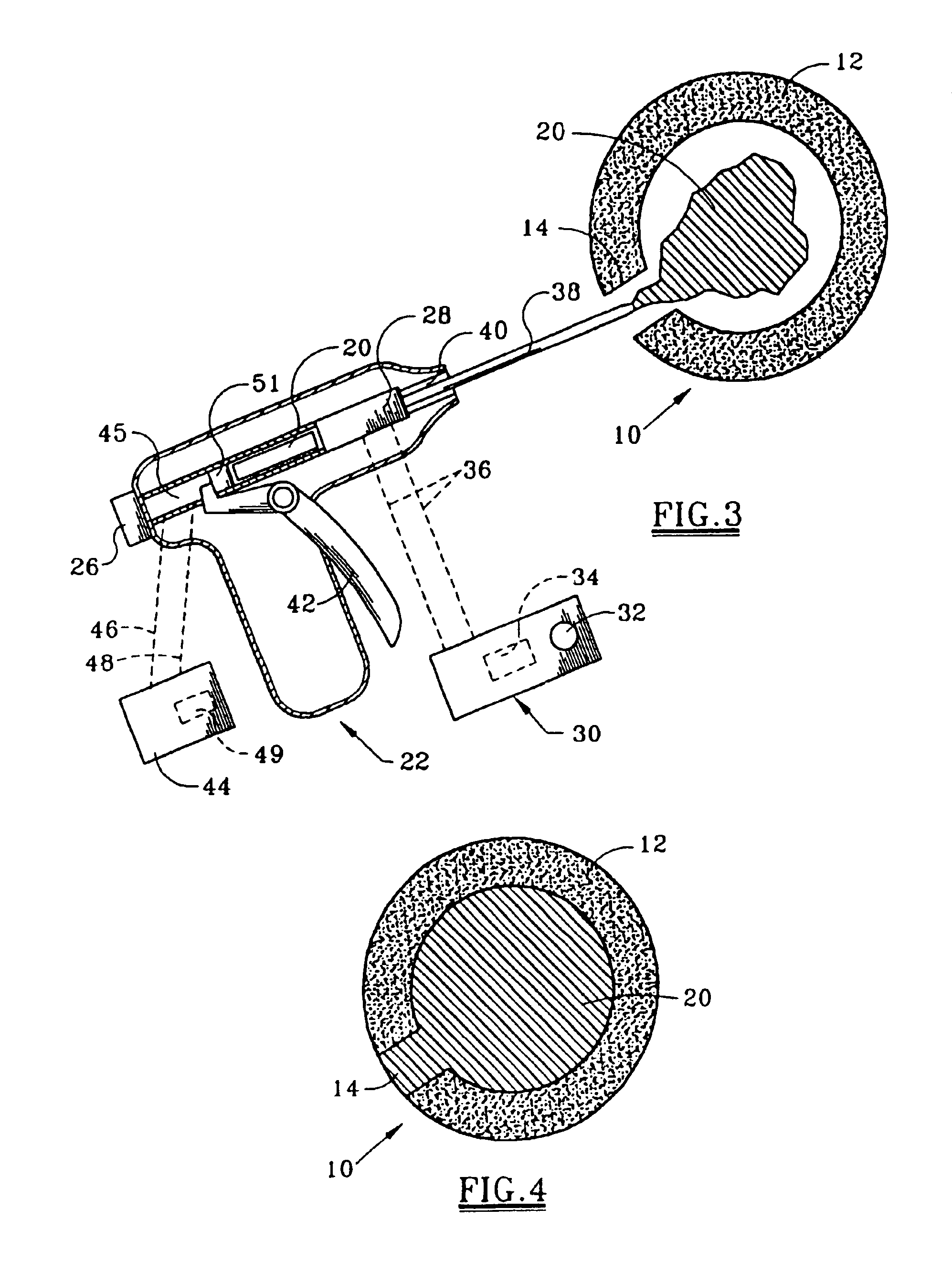
[0011]When the thermoplastic material is utilized to treat a ruptured annulus fibrosus, the nucleus pulposus is removed and the material removed is replaced by the heated thermoplastic material which sets at body temperature and provides sufficient resilience after setting to permit adequate motion and cushioning of the vertebrae. The cushioning effect of the gutta percha compound provides a semimobile disk as a buffer to a fusion to reduce the possibility of sequential iatrogenic disk degeneration. The thermoplastic material is injected within the potential nucleus pulposus space bordered by the annulus fibrosus to replace the removed nucleus pulposus by a needle of the injection device.
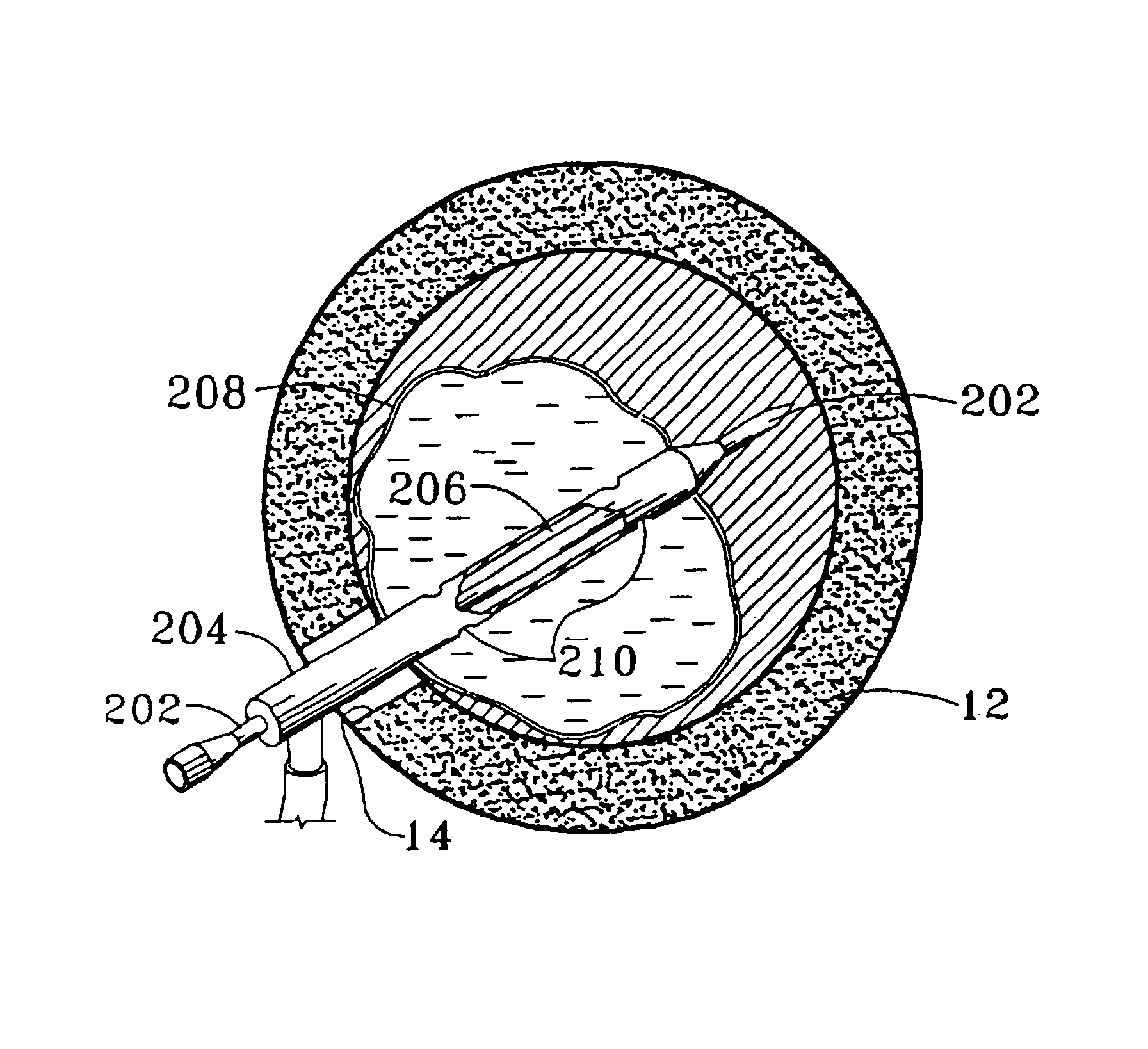
[0017]An additional object is to provide an apparatus to treat an annulus fibrosus of a spine in which an injection device heats the thermoplastic material for flow into the annulus fibrosus and another injection member is effective for expanding an expandable member in the annulus fibrosus.

Problems solved by technology

Intervertebral disks are prone to injury.
Due to the low blood supply to this area, intervertebral disks are slow to heal, and may not materially heal.
The effect of a ruptured or prolapsed annulus fibrosus may result in spasm, and neurological compromise, such as the compressed nerve and other compressible soft tissues, i.e. arteries, veins.
Degeneration of the condition may increase over time, resulting in chronic and debilitating pain.
This approach frequently leaves the patient immunologically and structurally compromised if not permanently disabled.
In addition, many patients suffer from scoliosis or lateral curvature of the spine.
Pain normally accompanies scoliosis and pain suppressants may result in an undesirable chemical dependency in some instances.

Method used


Image

  • Method and apparatus for treating intervertebral disks
  • Method and apparatus for treating intervertebral disks
  • Method and apparatus for treating intervertebral disks

Examples


embodiment

of FIG. 7

[0041]Also shown in FIG. 7 as an attachment is a disk dilator assembly generally indicated at 100 having a cylindrical chamber 102 with an inert fluid such as saline therein and a piston 108 for pressurizing the fluid. Disk dilator assembly 100 is designed for detachable connection to pressure chamber 76 of the injector device of FIG. 6 for the supply of hydraulic fluid for acting against piston 108. A detachable balloon dilator sleeve 106 extends about the extending end of needle 104 having lateral openings 107. Piston 108 is effective to pressurize the fluid for flow through openings107 for expansion of sleeve 106 as shown in broken lines in FIG. 7. Dilator sleeve 106 upon injection of needle 104 in a disk of the spine is expanded for exerting an expanding force against the disk.

Embodiment of FIGS. 8-10

[0042]Referring now to FIGS. 8-10 which are partially schematic, a further modification of an injection device and injection system is illustrated utilizing certain feature...


PUM

PropertyMeasurementUnit
Fractionaaaaaaaaaa
Percent by massaaaaaaaaaa
Volumeaaaaaaaaaa

Abstract

The method and apparatus as shown in FIGS. 8-10 in which a fluid expandable member (208) is positioned in concentric relation about a needle (202). The fluid expandable member (208) is expanded into the nucleus pulposus potential space bordered by the annulus fibrosus of an intervertebral disk. Then, thermoplastic material in a flowing state is injected by a needle (202) within the annulus fibrosus to collapse the fluid expandable member (208) and occupy the space formerly occupied by the fluid expandable member (208).

Description

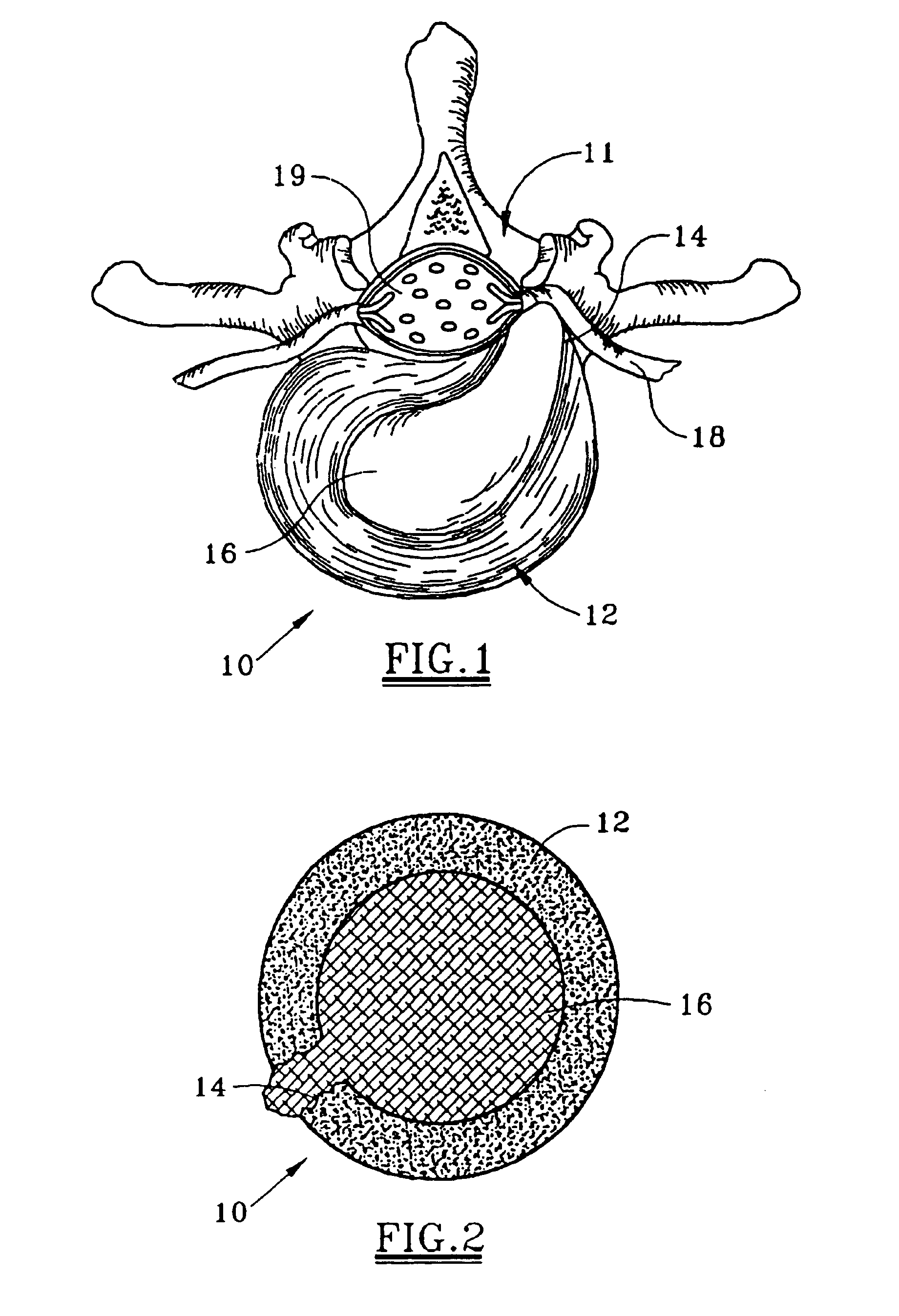
CROSS REFERENCE TO RELATED APPLICATIONS[0001]This is a continuation-in-part of pending application Ser. No. 09 / 456,375 filed Dec. 8, 1999; which is a continuation-in-part of application Ser. No. 09 / 274,217 filed Mar. 23, 1999; which is a continuation-in-part of application Ser. No. 09 / 255,372 filed Feb. 22, 1999.FIELD OF THE INVENTION[0002]This invention relates to surgical methods generally, and is more specifically related to a method and apparatus for treating intervertebral disks of mammals.BACKGROUND OF THE INVENTION[0003]The intervertebral disk is a disk with fibrosus bands occupying the space between two vertebrae. The anatomy of the disk provides a cushion to allow motion, limit motion and provide space, distancing the vertebra off the nerves and compressible tissue. Part of the vertebrae are bony blocks, which, when stacked one upon the other, form the anterior portion of the spine. The fibrosus band includes an outer annulus fibrosus which surrounds an inner nucleus pulpos...

Claims


Application Information

Patent Timeline
IPC IPC(8): A61B17/56A61B17/00A61B17/02A61B17/34A61B17/70A61B17/88A61F2/00A61F2/30A61F2/44A61F2/46
CPCA61B17/00491A61B17/3472A61B17/7097A61B17/8805A61B17/8822A61B17/8836A61B17/8855A61B2017/00539A61B2017/00557A61B2017/0256A61F2/441A61F2/442A61F2/4601A61F2/4611A61F2002/30065A61F2002/30563A61F2002/30583A61F2002/444A61F2002/4635A61F2002/4688A61F2210/0071A61F2210/0085A61F2002/465
Inventor ROSS, ANTHONY C.GUAGLIANO, PETER A.
Owner NUVASIVE
Learn More