
Active pulse blood constituent monitoring

a technology of active pulse and blood constituent, which is applied in the field of non-invasive systems, can solve the problems of difficult to determine the path length through a medium such as a fingertip or earlobe, low signal strength, and inability to detect glucose concentration, and achieve the effect of obscuring the ability to determine the arterial oxygen saturation

Inactive Publication Date: 2011-09-27
MASIMO CORP
View PDF195 Cites 607 Cited by
  • Summary
  • Abstract
  • Description
  • Claims
  • Application Information

AI Technical Summary

Benefits of technology

The patent text discusses the difficulties in accurately detecting glucose concentration in a fingertip or earlobe through a fleshy medium, such as blood. The natural heart beat and low signal strength make it difficult to determine the exact path length through the medium. The text proposes a solution by actively inducing a change in the flow of blood in the medium to obtain modulation, which can be used to determine the portion of the attenuated signal due to blood. This approach allows for accurate measurement of glucose concentration in the fingertip or earlobe.

Problems solved by technology

Due to the parameters required by the Beer-Lambert law, the difficulties in detecting glucose concentration arise from the difficulty in determining the exact path length through a medium (resulting from transforming the multi-path signal to an equivalent single-path signal), as well as difficulties encountered due to low signal strength resultant from a low concentration of blood glucose.
Path length through a medium such as a fingertip or earlobe is very difficult to determine, because not only are optical wavelengths absorbed differently by the fleshy medium, but also the signals are scattered within the medium and transmitted through different paths.
Thus, it is often very difficult to determine an exact path length through a fingertip or earlobe for each wavelength.

Method used


Image

  • Active pulse blood constituent monitoring
  • Active pulse blood constituent monitoring
  • Active pulse blood constituent monitoring

Examples


Embodiment Construction

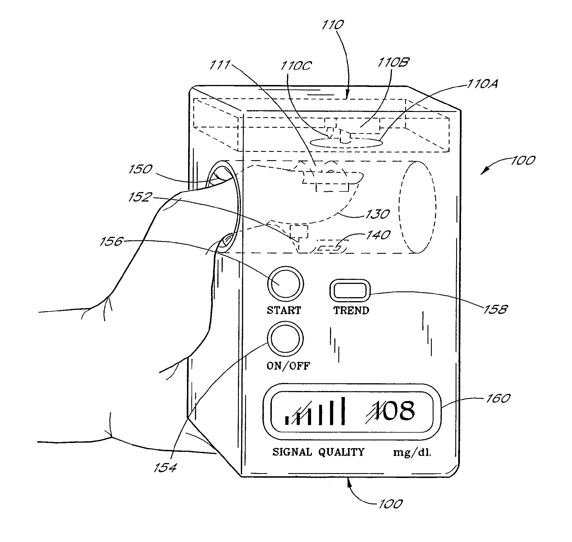
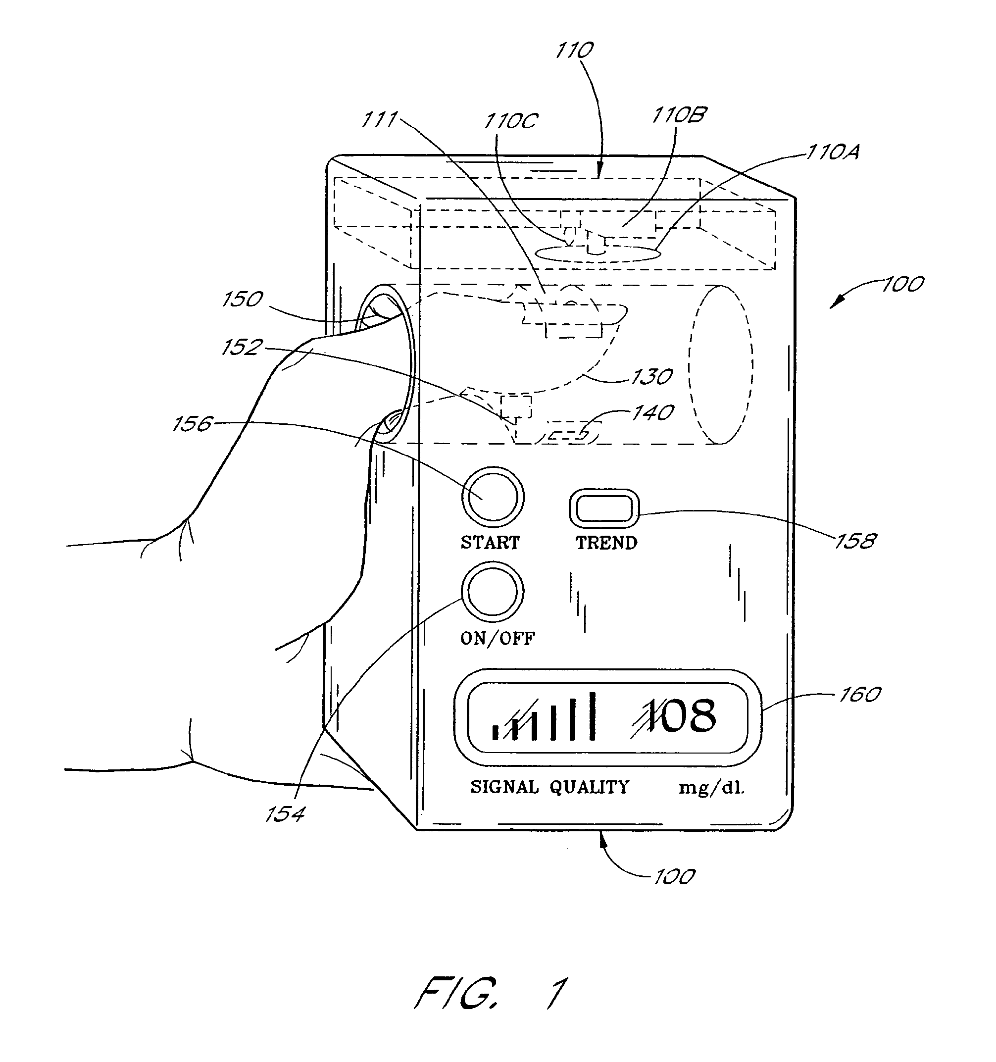
[0049]FIG. 1 depicts one embodiment of a blood glucose monitor system 100 in accordance with the teachings of the present invention. The glucose monitor 100 of FIG. 1 has an emitter 110 such as light emitting diodes or a light with a filter wheel as disclosed in U.S. patent application Ser. No. 08 / 479,164, now U.S. Pat. No. 5,743,262 Masimo. 014A) entitled Blood Glucose Monitoring System, filed on the same day as this application, and assigned to the assignee of this application, which application is incorporated by reference herein.

[0050]The filter wheel with a broadband light is depicted in FIG. 1. This arrangement comprises a filter wheel 110A, a motor 110B, and a broadband light source 110C. Advantageously, this unit can be made relatively inexpensively as a replaceable unit. The filter wheel is advantageously made in accordance with U.S. patent application Ser. No. 08 / 486,798 now U.S. Pat. No. 5,760,910 entitled Optical Filter for Spectroscopic Measurement and Method of Produci...


PUM


Abstract

A blood constituent monitoring method for inducing an active pulse in the blood volume of a patient. The induction of an active pulse results in a cyclic, and periodic change in the flow of blood through a fleshy medium under test. By actively inducing a change of the blood volume, modulation of the volume of blood can be obtained to provide a greater signal to noise ratio. This allows for the detection of constituents in blood at concentration levels below those previously detectable in a non-invasive system. Radiation which passes through the fleshy medium is detected by a detector which generates a signal indicative of the intensity of the detected radiation. Signal processing is performed on the electrical signal to isolate those optical characteristics of the electrical signal due to the optical characteristics of the blood.

Description

CROSS-REFERENCE TO RELATED APPLICATIONS[0001]Notice: More than one reissue application has been filed for the reissue of U.S. Pat. No. 7,239,905. The reissue applications are application Ser. No. 12 / 497,517 (the present application) and Ser. No. 13 / 047,740 (continuation of present application), both of which are reissues of U.S. Pat. No. 7,239,905.[0002]This application is a continuation of U.S. patent application Ser. No. 09 / 706,965, filed Nov. 6, 2000, now U.S. Pat. No. 6,931,268, issued Aug. 16, 2005, which is a continuation of U.S. patent application Ser. No. 09 / 190,719, filed Nov. 12, 1998, now U.S. Pat. No. 6,151,516, issued Nov. 21, 2000, which is a continuation of U.S. patent application Ser. No. 08 / 843,863, filed Apr. 17, 1997, now U.S. Pat. No. 5,860,919, issued Jan. 19, 1999, which is a continuation of U.S. patent application Ser. No. 08 / 482,071, filed Jun. 7, 1995, now U.S. Pat. No. 5,638,816, issued Jun. 17, 1997. The present application incorporates the foregoing discl...

Claims


Application Information

Patent Timeline
Patent Type & Authority Patents(United States)
IPC IPC(8): A61B5/00A61B5/1455
CPCA61B5/14532A61B5/1455A61B5/6826A61B5/6838A61B5/14552A61B2560/0462
Inventor KIANI-AZARBAYJANY, ESMAIELDIAB, MOHAMED KHEIRLEPPER, JR., JAMES M.
Owner MASIMO CORP
Learn More