
Reflector with resistant surface

a technology of reflective surfaces and reflective coatings, applied in the field of reflective coatings, can solve the problems of loss of energy, high purity, and increased precautions with increasing thickness of oxide coatings,

Inactive Publication Date: 2007-08-21
CONSTELLIUM SWITZERLAND
View PDF9 Cites 51 Cited by
  • Summary
  • Abstract
  • Description
  • Claims
  • Application Information

AI Technical Summary

Benefits of technology

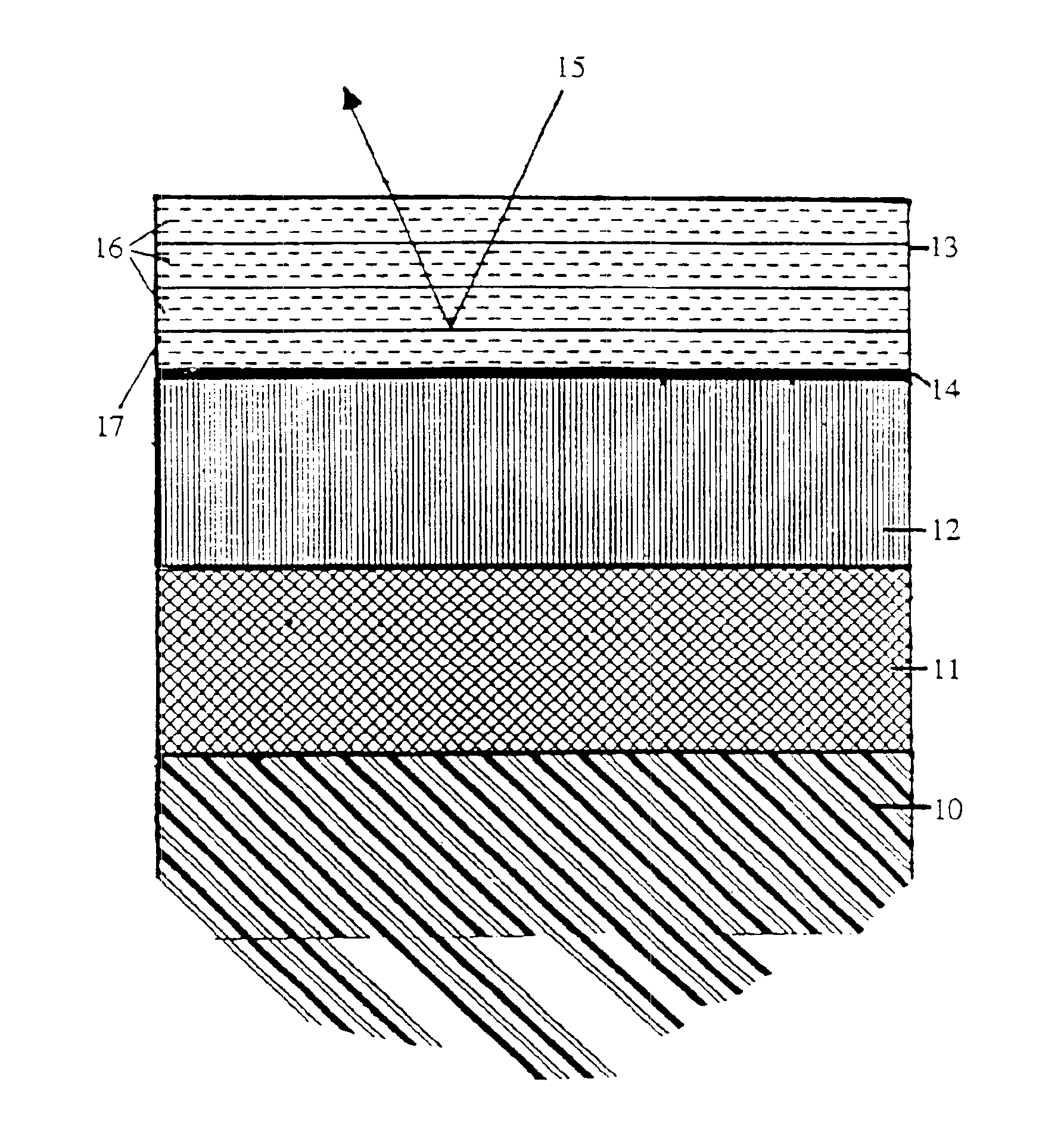
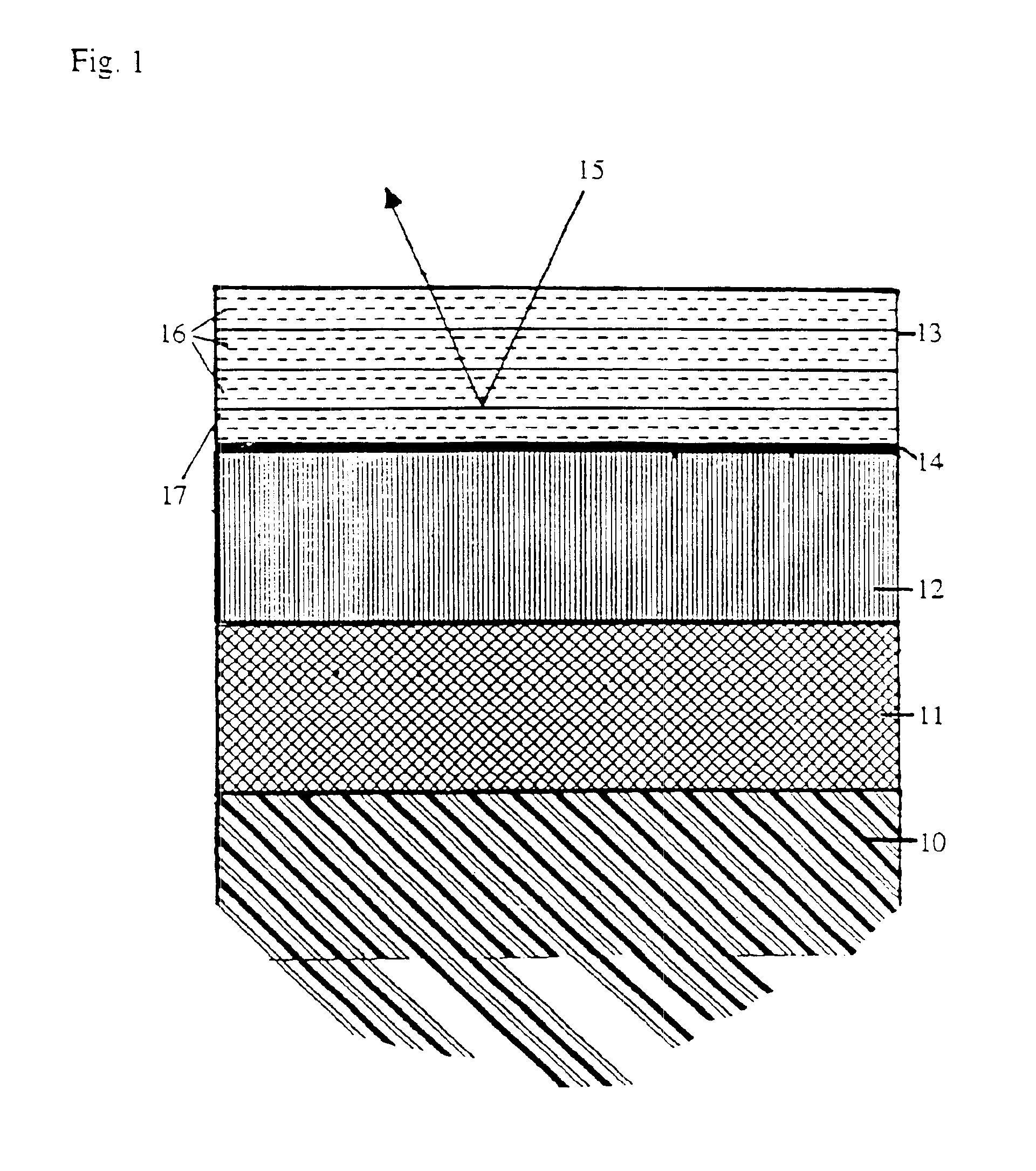
[0013]c) a metallic reflective layer,where layer a) is deposited on the reflector body and increases the strength of bonding to the layers lying above it, and layer b) effects a flattening and an increase in the mechanical strength of the above lying layer c).DETAILED DESCRIPTION OF THE INVENTION
[0031]The electrolytic production of such layers a) allows the thickness of the layer to be regulated very precisely. The maximum thickness of aluminium oxide barrier layer achieved is in nanometers (nm) approximately the value of the applied voltage (V), i.e. the maximum thickness of layer is linearly dependent on the anodising voltage—whereby the voltage drop at the outer layer has to be taken into consideration. The exact value of the maximum layer thickness achieved as a function of the applied direct voltage U and—taking into account the voltage drop at the outer layer—can be determined by a simple trial and lies in the region of 1.2 to 1.6 nm / V. The exact value of layer thickness is a function of the applied voltage, the electrolyte used i.e. its composition and its temperature.

Problems solved by technology

Anodising processes are chemical treatments which suffer the disadvantage of requiring considerable precaution in order to avoid contamination of the environment The extent of these precautions increases with increasing thickness of the oxide layer.
The known processes have the further disadvantage that high purity, expensive bright-finish alloys based on aluminium of very high purity have to be employed.
This represents a loss in energy.
Such a layer system, however, suffers the disadvantage that the surfaces are very sensitive to physical attack, such as mechanical or chemical attack e.g. by corrosive media.
This is also a possible way of arriving at reflective aluminium materials without having to employ anodising; the layered structure described in EP-A-0 568 943 is, however, not resistant to mechanical effects and corrosion to the extent desired.

Method used


Image

  • Reflector with resistant surface
  • Reflector with resistant surface

Examples


example

[0071]1. A pre-treatment layer is deposited on an aluminium strip in a continuous process. For that purpose an aluminium strip (Al 99.8, Ra 0.08 μm), 500 mm wide and 0.3 mm thick is continuously anodised at 40 m / min. In that process the strip is exposed to the following treatments:[0072]a) Degreasing at pH 9-9.5, at approx. 50° C. and bonder V6150 / 01,[0073]b) rinsing with tap water (room temperature),[0074]c) anodising in 20% H2SO4 at 85° C. and 20V,[0075]d) rinsing in tap water at 50° C. and[0076]e) rinsing in deionised water at approx. 85° C.

[0077]The strip bearing the pre-treatment layer, in the present example the pre-anodised strip, is coated with the functional layer at 40 m / min in a coil coating process and counter-flowing immersion and deposition rolls and dried in a continuous oven at an oven temperature of 200 to 250° C. for approx. 10 to 15 sec. The temperature of the metal (measured using thermoelements on the non-coated substrate) was between 195 and 216° C.

[0078]The ri...


PUM

PropertyMeasurementUnit
thicknessaaaaaaaaaa
thicknessaaaaaaaaaa
thicknessaaaaaaaaaa

Abstract

Reflectors, for example, for lamps used for technical lighting purposes, having a surface which is resistant to mechanical and chemical attack and has high total reflectivity. The body (10) of the reflector, which is, for example, a rolled aluminum product such as a foil, a strip of a sheet, has a surface layer in the form of a layer system containing (a) a pretreatment layer (11), onto which is deposited (b) a functional layer (12) with silanes, having organo-functional groups, of a metal compound, and onto which is deposited (c) a metal-containing reflective layer (13). Layer (a) is deposited on the reflector body and increases the strength of bonding to the above lying layers (a) and (b). Layer (b) effects a flattening and increase in the mechanical strength of the above lying layer (c). The pretreatment layer can be a layer produced by anodic oxidation. The functional layer (b) can be a sol-gel layer. The reflective layer (c) can be a metallic reflective layer, in some cases with one or more protective layers, which are deposited, e.g., by vacuum thin layer deposition process.

Description

BACKGROUND OF THE INVENTION[0001]1. Field of the Invention[0002]The present invention relates to a reflector having, on a reflector body, a surface which is resistant to mechanical and chemical attack and exhibits high total reflectivity. The invention relates also to a process for its manufacture and the use of such reflectors with a resistant surface layer.[0003]2. Background Art[0004]Known is the production of bright finish strips e.g. of high purity aluminium or AlMg alloys based on aluminium having a purity of 99.8% and higher, such as e.g. 99.9%, and roll surfaces that produce diffuse or directionally reflected light depending on the application. To increase the directional reflectivity (degree of brightness) of such strips, it is also known to brighten the strips chemically or electrolytically, then to create a e.g. 1.5 μm thick protective layer by anodic oxidation.[0005]Anodising processes are chemical treatments which suffer the disadvantage of requiring considerable precau...

Claims


Application Information

Patent Timeline
Patent Type & Authority Patents(United States)
IPC IPC(8): B32B15/08B32B15/04G02B5/08C09D183/04C25D11/18G02B1/10
CPCC23C28/00C25D11/18G02B5/0866Y10T428/24967Y10T428/265Y10T428/24975
Inventor FUCHS, ROMANSCHOTTNER, GERHARDSANDROCK, JOHANNES MARTIN
Owner CONSTELLIUM SWITZERLAND
Learn More