
Image forming apparatus

Inactive Publication Date: 2003-04-29
OLYMPUS OPTICAL CO LTD
View PDF5 Cites 12 Cited by
  • Summary
  • Abstract
  • Description
  • Claims
  • Application Information

AI Technical Summary

Benefits of technology

It is an object of the present invention to provide a compact image forming apparatus capable of stably and efficiently conveying a sheet with a simple construction and having a high operability.

Problems solved by technology

In these conventional image forming apparatuses, however, a large space is required to arrange the three drawer trays on the operation side, and a large area on the operation side is occupied by these drawer trays.
This makes operations in one direction (operation side) of an apparatus difficult.
Also, when a sheet jam occurs in the conventional image forming apparatuses, it is necessary to pull out the corresponding drawer tray and this is troublesome for a user.
Additionally, the sheet may be torn off halfway when the user pulls out the drawer tray.
However, this increases the dimensions and the cost of an apparatus.
Furthermore, if all drawer trays are pulled out, the stability of the apparatus decreases.
To solve these problems, if an apparatus is so designed that all drawer trays cannot be simultaneously pulled out, the operability of the apparatus suffers.
This makes the posture which the user takes when mounting the sheet roll unnatural and thereby increases the burden of the user when he or she sets the sheet roll.
In addition, the use of drawer trays increases the sheet conveyance distance to the recording unit, and this increases the time required for a sheet to reach the recording unit.
Also, a large error appears in the sheet position when the sheet passes through the recording unit.
However, the moving length of a sheet in the conveyance direction is very small compared to the width of the sheet.
This makes accurate detection of a skew difficult.
If the sheet has a slack or the like, therefore, the recording means may contact and damage the sheet in some cases.
If the recording width of a recording means is large and a high recording speed is necessary, the radius of curvature of the platen roller cannot be ignored.
Accordingly, a platen roller with a large diameter is necessary, with the result that a large space is required to accommodate this platen roller and the size of the apparatus is increased.
Also, it is difficult to maintain the accuracy of the guide constant throughout the width because of the influence of parts accuracy and thermal expansion by environments.
For example, in a method of conveying a sheet by drawing the sheet to a belt by suction, it is difficult to draw the sheet to the belt by suction with no slip because of the influence of inertia of the sheet or the like.
There is another problem that the conveyance of the belt is not constant due to slip or the like cause.
When a sheet is also conveyed downstream of the recording unit, image recording cannot be performed until the sheet reaches a conveying means on the downstream side, resulting in a low recording efficiency.
Additionally, since a non-recorded portion is formed on the leading edge of a sheet, the effective recording area is restricted.
This makes efficient image recording impossible.
This makes the apparatuses of this type inconvenient in actual use.
On the other hand, in apparatuses in which sheets are stocked by dropping them into a stocker, lower sheets are smashed to wrinkle by the weights of sheets falling on them.
Also, coated sheets are primarily used as sheets for an inkjet method, and these coated sheets easily form paper dust when cut.
When dust particles thus adhere to the recording head, it is no longer possible to normally eject ink.
This problem of paper dust is significant in an apparatus having a cutting means above a recording unit.
Moreover, in the conventional image forming apparatuses, the set positions of sheet rolls are determined and hence it is not possible to flexibly change the set positions in accordance with the use condition or the objective of use.
For example, it is impossible to set only a large-size sheet and record a large image on the sheet or to change the set position of a small-size sheet roll to a desired position.

Method used


Image

  • Image forming apparatus
  • Image forming apparatus
  • Image forming apparatus

Examples


first embodiment

An image forming apparatus according to the present invention will be described below with reference to the accompanying drawings. Note that the image forming apparatus of this embodiment is so designed as to be able to record a desired image on a sheet of a predetermined size, and it is possible to use, e.g., recording paper, a sheet of paper, a plastic film, or cloth as the sheet.

The embodiment will be described below by taking an image forming apparatus using a sheet of paper as an image recording sheet as an example.

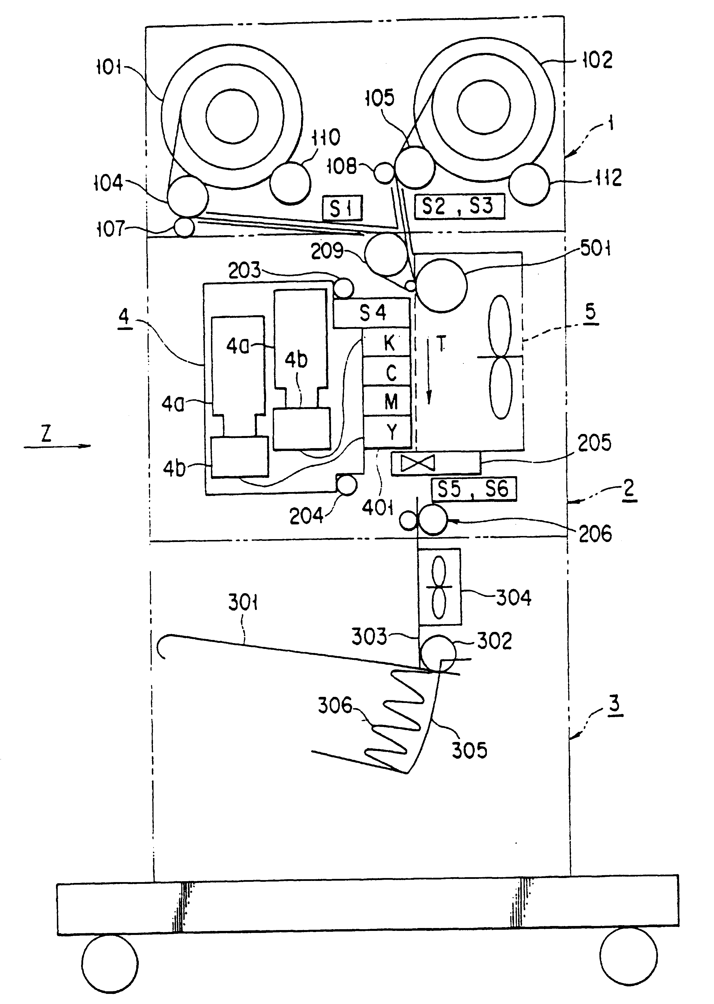
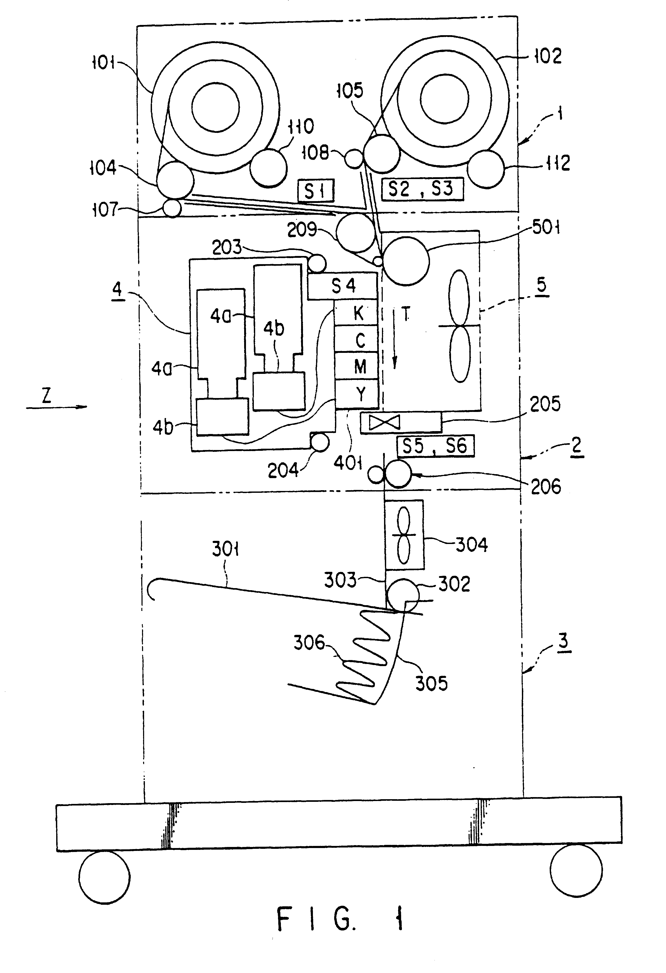
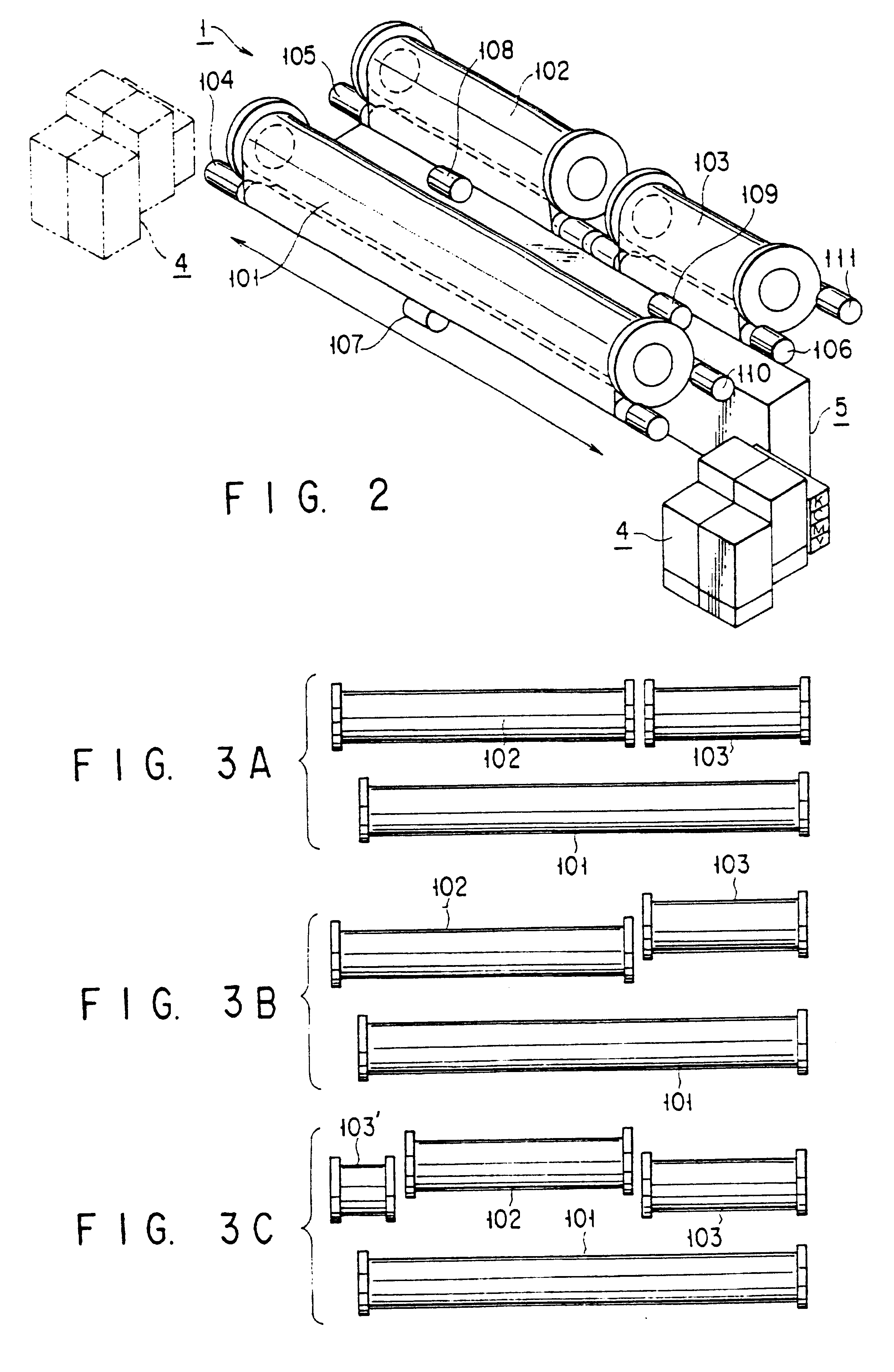
As shown in FIG. 1, the image forming apparatus of this embodiment includes a paper feed station 1, a recording station 2, and a processing station 3. The paper feed station 1 can accommodate a plurality of roll sheets each formed by winding a sheet of a predetermined size into a roll (although only two roll sheets 101 and 102 are shown in FIG. 1, this embodiment uses first, second, and third roll sheets 101, 102, and 103 as shown in FIG. 2). The recording station 2 ...

second embodiment

An image forming apparatus according to the present invention will be described below. The image forming apparatus of this embodiment is so designed as to be able to record a desired image on a sheet of a predetermined size. It is possible to use, e.g., recording paper, a sheet of paper, a plastic film, or cloth as the sheet.

In the following explanation, an image forming apparatus using a sheet of paper as an image recording sheet will be described as an example.

As shown in FIGS. 21 and 22, the image forming apparatus of this embodiment includes a paper feed station 1, a recording station 2, and a processing station (not shown). The paper feed station 1 can accommodate a plurality of roll sheets each formed by winding a sheet of a predetermined size into a roll. The recording station 2 records a desired image on a sheet fed from the paper feed station 1. The processing station delivers the sheet on which the image is recorded by the recording station 2.

In this embodiment, it is assu...


PUM


Abstract

An image forming apparatus includes a paper feed station from which sheets can be fed from a plurality of roll sheets only by placing the roll sheets in the station, a recording station for recording desired images on the sheets, and a processing station for delivering the sheets on which the images are recorded. The recording station includes a platen roller and a driving pinch roller for pushing and conveying a fed sheet while the sheet is drawn by suction by a suction chamber, a carriage unit for recording an image on the sheet on the suction chamber while moving along the sheet, and a pair of paper delivery rollers for delivering the sheet on which the image is recorded. The processing station includes a table on which the delivered sheets can be sequentially stacked in a predetermined position, and a biasing spring for biasing the pivotal distal end portion of the table.

Description

BACKGROUND OF THE INVENTION1. Field of the InventionThe present invention relates to an image forming apparatus applied to, e.g., a printer or a plotter, which is capable of continuously recording a desired image on sheets of various sizes.2. Description of the Related ArtConventionally, the following two methods are known as methods of forming images on sheets of various sizes (e.g., sheets of A sizes such as A4, A3, A2, A1, and A0).The first method is to set only an A0-size sheet roll (which is formed by winding an A0-size sheet into a roll) in an image forming apparatus and cut the sheet into a desired size after an image is formed. The second method is to set a plurality of sheet rolls of various sizes in an image forming apparatus and cut each sheet into a desired length after an image is formed.To form desired images on sheets of various sizes from A4 to A0 by using these methods, three sheet rolls with different widths are necessary. More specifically, a 297-mm wide sheet rol...

Claims


Application Information

Patent Timeline
IPC IPC(8): B41J2/01B41J15/18B41J11/00B41J11/06B41J15/02B41J11/02
CPCB41J2/01B41J11/0085B41J11/06B41J15/02B41J15/18
Inventor YAMADA, TAKAHISAKUMAGAI, YUKITAKA
Owner OLYMPUS OPTICAL CO LTD
Learn More