
Method for designing coil systems for generation of magnetic fields of desired geometry, a magnetic resonance imaging or magnetoencephalography apparatus with a coil assembly and a computer program

a coil system and magnetic field technology, applied in the field of magnetic imaging technologies, can solve the problems of large volume, large delay, and protection of measuring devices, and achieve the effect of effectively compensating different kinds of active interference situations and large volum

Active Publication Date: 2018-05-22
MEGIN OY
View PDF17 Cites 3 Cited by
  • Summary
  • Abstract
  • Description
  • Claims
  • Application Information

AI Technical Summary

Benefits of technology

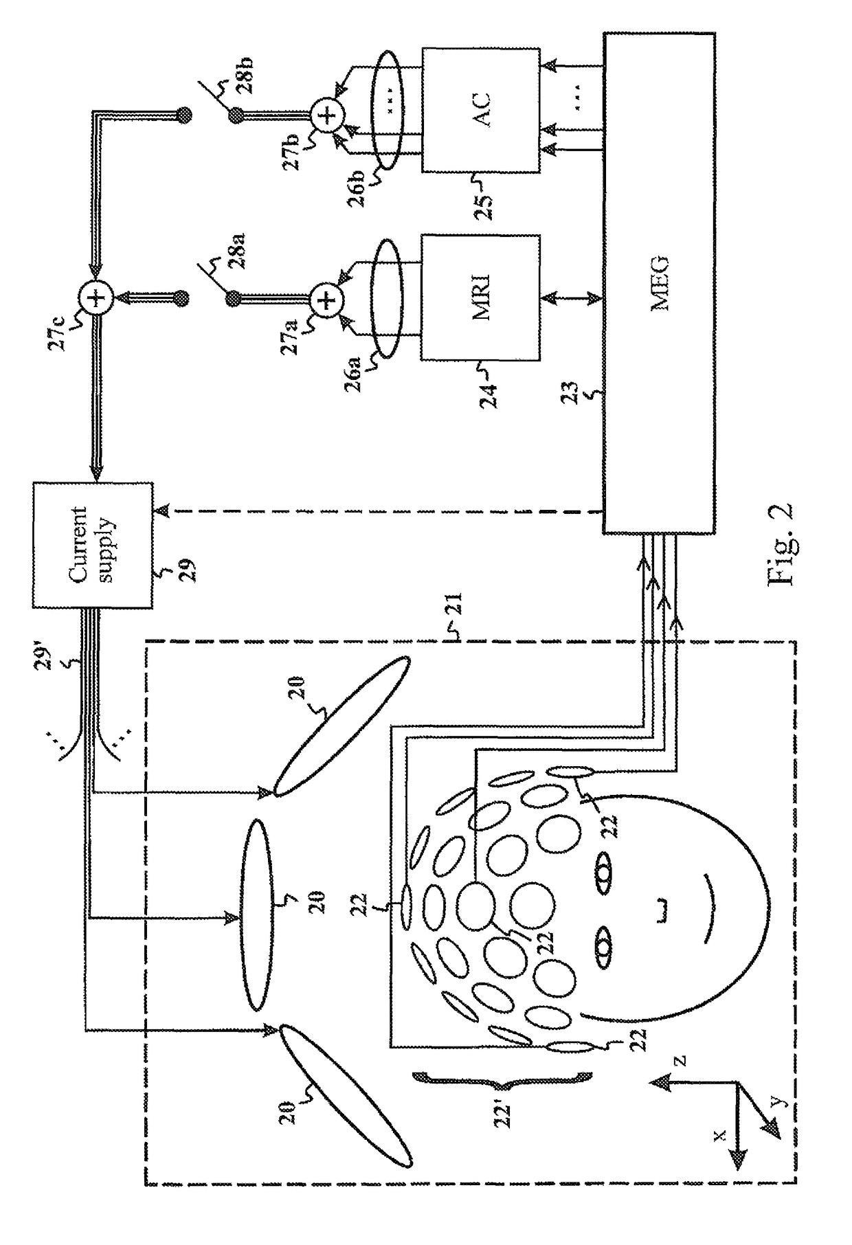
[0045]In an embodiment of the present invention, the control means is configured to use the linear combinations of the dominant external interference components as feedback field shapes in an active compensation system, where the linear combinations forming the feedback field shapes, and the locations and orientations of the sensors, are chosen so that the coupling between simultaneously operating feedback loops is minimized.
[0051]The advantages of the present invention are that with the presented coil assembly design method we can produce desired and accurate magnetic fields with the assembly which is able to effectively compensate different kinds of active interference situations over a relatively large volume. A further advantage is that this design method is mainly implemented with matrix algebra, and therefore the application of the invention can be performed in a straight-forward manner in the existing control logic or processor of the MEG device, for instance. A further advantage is that the measuring volume to be compensated is large, and finally, the method is even applicable inside the magnetically shielding rooms which typically include magnetic materials, previously interfering the active compensation systems significantly.

Problems solved by technology

One of the main problems in this technique is the protection of the measuring device against the environmental magnetic interference the strength of which may exceed the signals of interest by seven to eight orders of magnitude.
Placing the coils outside of the MSR would cause extra delay and lead to unstable feedback loop.
For practical applications this coil design problem is further complicated by the presence of magnetic materials in the vicinity of the coils, and specifically in MEG, by the presence of the MSR.
This results in a considerable scattered field that is added to the direct field of the coils.
Therefore designing the coil assembly by a mere calculation would require measurement and characterization of the room structure and magnetic properties of the wall elements in such a detailed manner that it is practically impossible.

Method used


Image

  • Method for designing coil systems for generation of magnetic fields of desired geometry, a magnetic resonance imaging or magnetoencephalography apparatus with a coil assembly and a computer program
  • Method for designing coil systems for generation of magnetic fields of desired geometry, a magnetic resonance imaging or magnetoencephalography apparatus with a coil assembly and a computer program
  • Method for designing coil systems for generation of magnetic fields of desired geometry, a magnetic resonance imaging or magnetoencephalography apparatus with a coil assembly and a computer program

Examples


case 1

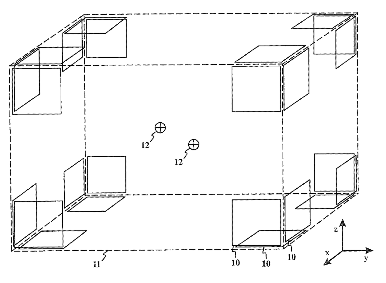
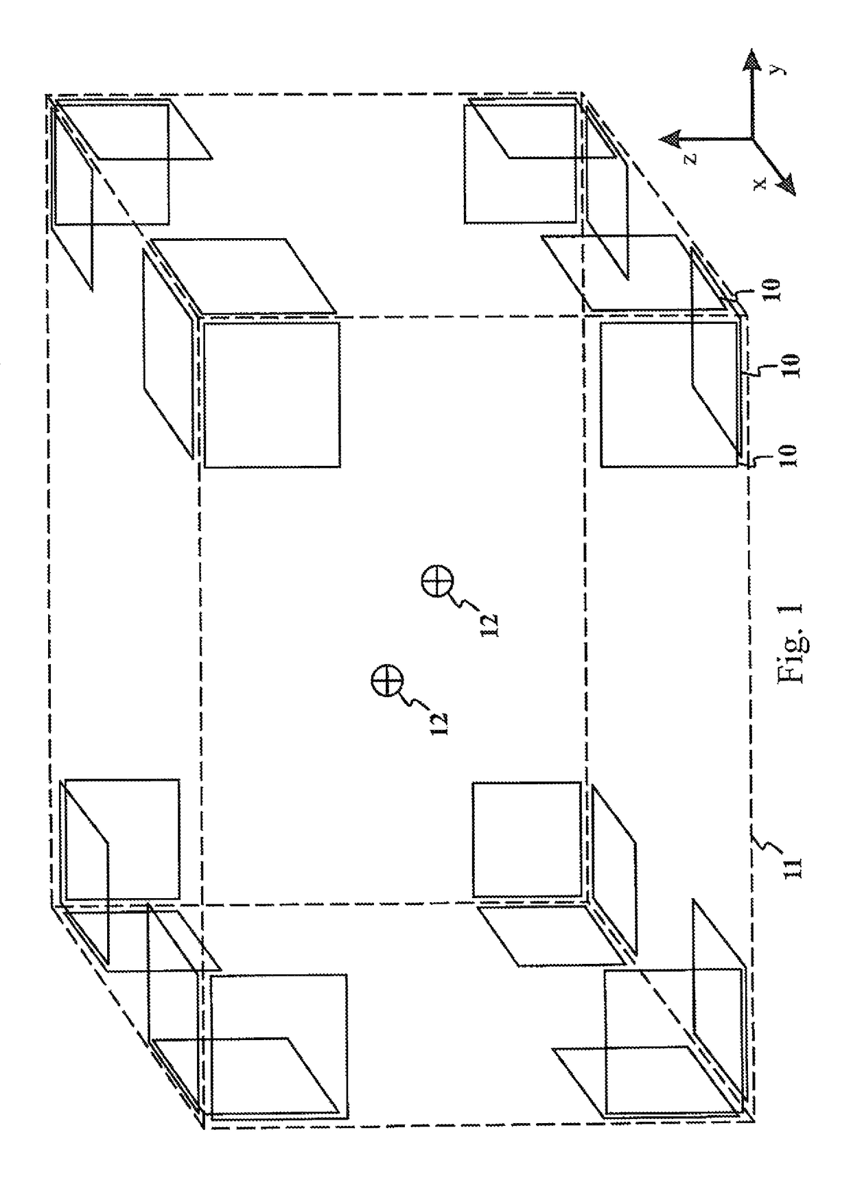
[0069) is the simplest. Here the number of coils (available “degrees of freedom”) is the same as the number of quantities to control (the three field components and their 5+7 independent derivatives at the origin). In this case M is a 15×15 square matrix and equation (2) has a unique solution. The current vector I needed to create a uniform field in the z-direction, Bz, for example, is obtained from equation (2) by using the column vector B={0, 0, 1, 0, . . . , 0}. The resulting field is precisely (with numerical accuracy) along the z-axis and all its derivatives up to the second derivatives vanish at the origin.

[0070]In case 2) the system defined by equation (1) is underdetermined. The number of coils is larger than the number of quantities to be controlled. In this case equation (1) has an infinite number of solutions I. The solution given by the Moore-Penrose pseudo-inverse is the one that has the smallest Euclidian norm, that is, the smallest length of the vector I. In this case...


PUM


Abstract

The present invention introduces a method, apparatus and computer program for magnetic resonance imaging or magnetoencephalography applications in order to control currents of a coil assembly (20), and thus achieving desired magnetic fields precisely in the measuring volume (21). The approach is an algebraic method where a field vector is generated for the test currents of each coil (20). Vector and matrix algebra is applied and a linear set of equations is formed. Field components and their derivatives up to the desired order can be taken into account. Principal component analysis or independent component analysis can be applied for determination of the dominant external interference components. By checking the condition value for the matrix (33, 45), it is possible to investigate whether a reasonable solution of currents for desired magnetic fields is possible to achieve. Finally, solved currents can be installed into a current supply unit (29) feeding the coils of the assembly (20). The invention can be applied as an active compensation feature for different interference shapes in the MEG application (25), or for the precise creation of the fields and gradients in the MRI application (24).

Description

FIELD OF THE INVENTION[0001]The invention relates to magnetic imaging technologies and specifically to creation of magnetic fields of specified, geometrically precise shape over a large volume in space.BACKGROUND OF THE INVENTION[0002]Magnetic fields of precise geometry are needed in medical magnetic imaging applications, like magnetic resonance imaging (MRI) and magnetoencephalography (MEG). Recently, also combination of the two imaging techniques has been proposed (“Microtesla MRI on the human brain combined with MEG”, Vadim S. Zotev et al, Journ. Mag. Res. 194, pp 115-120, 2008).[0003]In the MRI method the part of the human body that is studied is exposed to a uniform magnetic field, and to gradients of the field for decoding of the spatial information contained in the MRI signal. The geometry of the measuring field essentially contributes to the signal quality and geometric precision of the resulting MRI image. An ideal measuring field is free of field derivatives higher than fi...

Claims


Application Information

Patent Timeline
Patent Type & Authority Patents(United States)
IPC IPC(8): G01R33/385G01R33/38A61B5/00G01R33/28G01R33/381G01R33/025A61B5/055A61B5/04G06F17/12G01R33/3875G01R33/48G01R33/421
CPCG06F17/12A61B5/0035A61B5/04008A61B5/055G01R33/025G01R33/381G01R33/28G01R33/4808G01R33/385G01R33/3875G01R33/4215A61B5/245G01R33/20
Inventor SIMOLA, JUHATAULU, SAMU
Owner MEGIN OY
Learn More