Communication device and MIMO (multi-input multi-output) antenna system therein

Inactive Publication Date: 2013-11-14
ACER INC
View PDF6 Cites 10 Cited by
  • Summary
  • Abstract
  • Description
  • Claims
  • Application Information

AI Technical Summary

Benefits of technology

The patent describes a communication device with a ground plane and an antenna system. The antenna system includes two antennas located at the edge of the ground plane and operating in different frequency bands. The ground plane has a slit that reduces surface currents and improves the isolation between the two antennas. The slit is parallel to the ground plane and has a projection that covers the first antenna. The technical effect of this invention is to improve the isolation between the antennas without affecting their efficiency.

Problems solved by technology

The drawbacks of the traditional method include decreased antenna efficiency and degraded radiation performance.
In addition, if these antennas are operated in an LTE700 band (from 704 MHz to 787 MHz), the isolation element is required to become resonance at about 700 MHz and hence requires a large element size, which greatly increases the size of the whole antenna system.
Integration of such an antenna system in the limited space inside the mobile device is a challenge for an antenna designer.

Method used


Image

  • Communication device and MIMO (multi-input multi-output) antenna system therein
  • Communication device and MIMO (multi-input multi-output) antenna system therein
  • Communication device and MIMO (multi-input multi-output) antenna system therein

Examples


Embodiment Construction

[0019]In order to illustrate the foregoing and other purposes, features and advantages of the invention, the embodiments and figures thereof in the invention are shown in detail as follows.

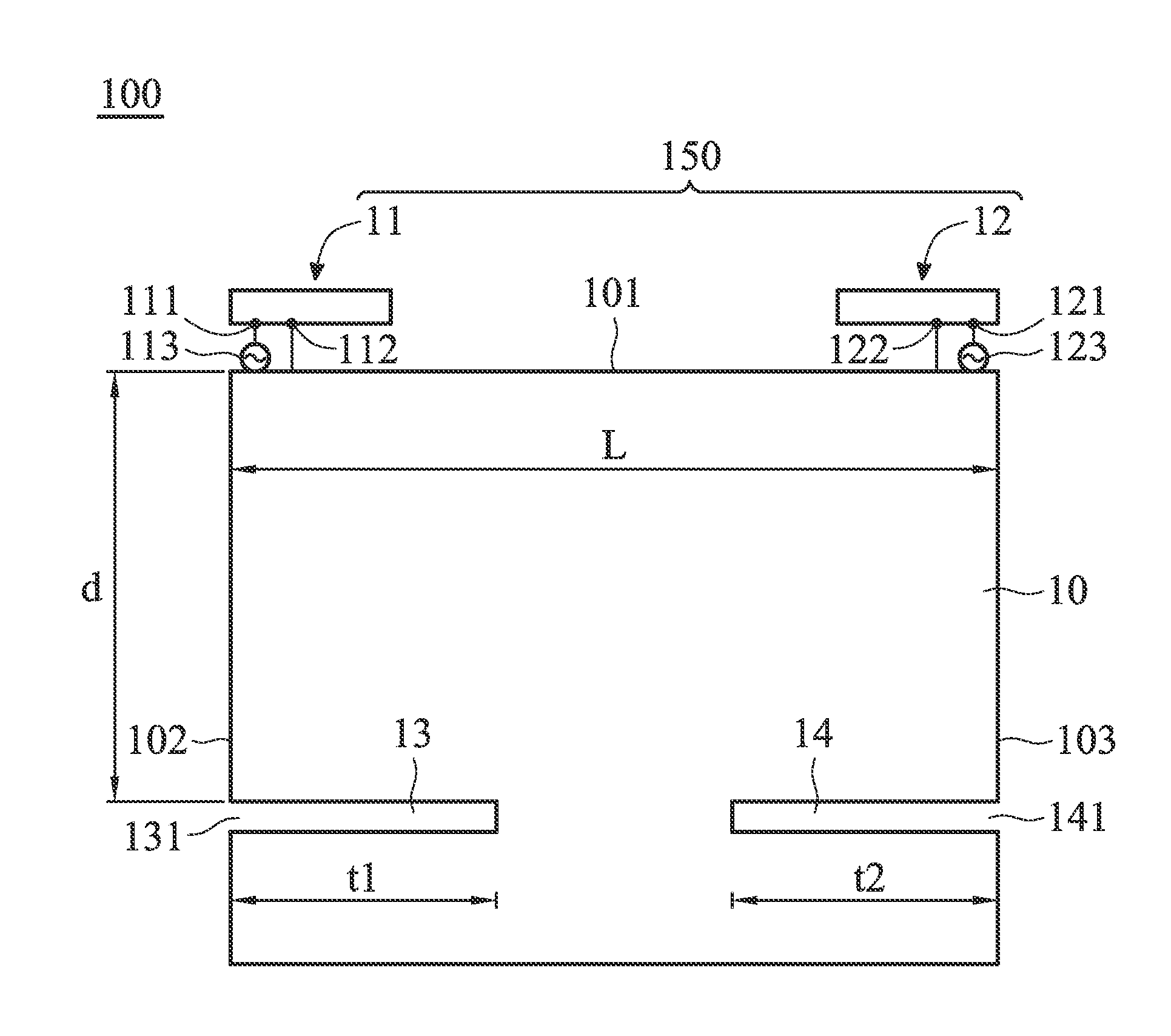
[0020]FIG. 1 is a diagram for illustrating a communication device 100 according to a first embodiment. In the embodiment, the communication device 100 comprises a ground plane 10 and an antenna system 150. The ground plane 10 has a first edge 101, a second edge 102, and a third edge 103, wherein the second edge 102 and the third edge 103 are both adjacent to the first edge 101. The antenna system 150 comprises at least a first antenna 11 and a second antenna 12. The first antenna 11 has a feeding end 111 and a shorted end 112. A signal source 113 is configured as a feeding signal source of the first antenna 11, and the signal source 113 is electrically coupled to the feeding end 111. The shorted end 112 is electrically coupled to the ground plane 10. Similarly, the second antenna 12 has a feeding ...


PUM


Abstract

A communication device including a ground plane and an antenna system is provided. The antenna system includes at least two antennas, which are both located at a first edge of the ground plane and operate in at least a first band. The ground plane has at least one slit, and an open end of the slit is located at a second edge adjacent to the first edge. The open end of the slit has a distance of at least 0.2 wavelength of a frequency in the first band to the first edge. When the antenna system operates in the first band, the slit can attract excited surface currents on the ground plane, thereby causing weaker surface currents flowing along the first edge of the ground plane. The coupling between the at least two antennas in the antenna system is hence decreased.

Description

CROSS REFERENCE TO RELATED APPLICATIONS[0001]This application claims priority of Taiwan Patent Application No. 101116785 filed on May 11, 2012, the entirety of which is incorporated by reference herein.BACKGROUND OF THE INVENTION[0002]1. Field of the Invention[0003]The disclosure generally relates to a communication device, and more particularly, relates to a communication device comprising a MIMO (Multi-Input and Multi-Output) antenna system with high isolation.[0004]2. Description of the Related Art[0005]As people demand more and more data transmission, related communication standards are supporting higher and higher data transmission rates. For example, IEEE 802.11n can support MIMO technology to increase transmission rates. The related communication standards, such as LTE (Long Term Evolution), also support MIMO operations. As a matter of fact, it is a future trend to use multiple antennas in a mobile device. However, since multiple antennas are to be disposed in a limited space...

Claims


Application Information

Patent Timeline
IPC IPC(8): H01Q1/48
CPCH01Q1/243H01Q1/48H01Q1/521H01Q21/28
Inventor WONG, KIN-LUWU, TSUNG-JU
Owner ACER INC
Why Eureka
Try Eureka