Light gas gun

a light gas and gun technology, applied in the field can solve the problems of difficult transition to a man-portable weapon, difficult to convert the design to a fieldable weapon system, and difficulty in rapid fire, so as to reduce the acoustic signature of light gas guns, increase the range of guns, and increase the muzzle velocity of guns

Active Publication Date: 2018-03-13
BERGERON DAVID WAYNE
View PDF3 Cites 8 Cited by
  • Summary
  • Abstract
  • Description
  • Claims
  • Application Information

AI Technical Summary

Benefits of technology

[0008]The light gas gun of this invention is a compressed gas weapon or launcher that uses helium or hydrogen as the working fluid. The light gas gun described herein provides a unique and potentially devastating weapon that will provide the operator greater range, superior lethality, more stealth, and ultimately greater survivability than any other weapon of its kind. The gun is designed to provide muzzle velocities greater than any conventional firearm of the same caliber currently in use. The embodiments are capable of firing spin-stabilized and non-spin stabilized projectiles.
[0009]The gun of this invention consists of four primary elements: the frictionless barrel assembly, the breech assembly, the muzzle valve assembly, and the light gas that is used as the propellant. The barrel assembly uses gas bearings to minimize projectile assembly contact with the barrel walls. The gas bearings virtually eliminate friction with the barrel, thus greatly reducing barrel wear. Given the substantially increased muzzle velocities capable with a light gas gun, this is an enabling feature.

Problems solved by technology

These combustion products can cause fouling of the pump tube, making it impractical to convert the design to a fieldable weapon system.
It also uses a single use diaphragm, making rapid fire difficult.
The design has elements that would lend itself to large guns such as artillery or naval guns, but would still be difficult to transition to a man-portable weapon.
In addition, the corrosive nature of anhydrous ammonia or water would create severe wear within the breech, making the fielded system unreliable and decreasing maintainability.
The complexity of the system and the necessity of evacuating the barrel preclude its use as a fieldable weapon system.
The solution requires considerable hardware be added to the projectile, making it unsuitable for a small caliber round.
None of the systems described in the prior art is adaptable to a man-carried weapon system.
Each has limitations that preclude sustained rates of fire, light weight, and the simplicity and reliability necessary for a weapon system.

Method used


Image

  • Light gas gun
  • Light gas gun
  • Light gas gun

Examples


first embodiment

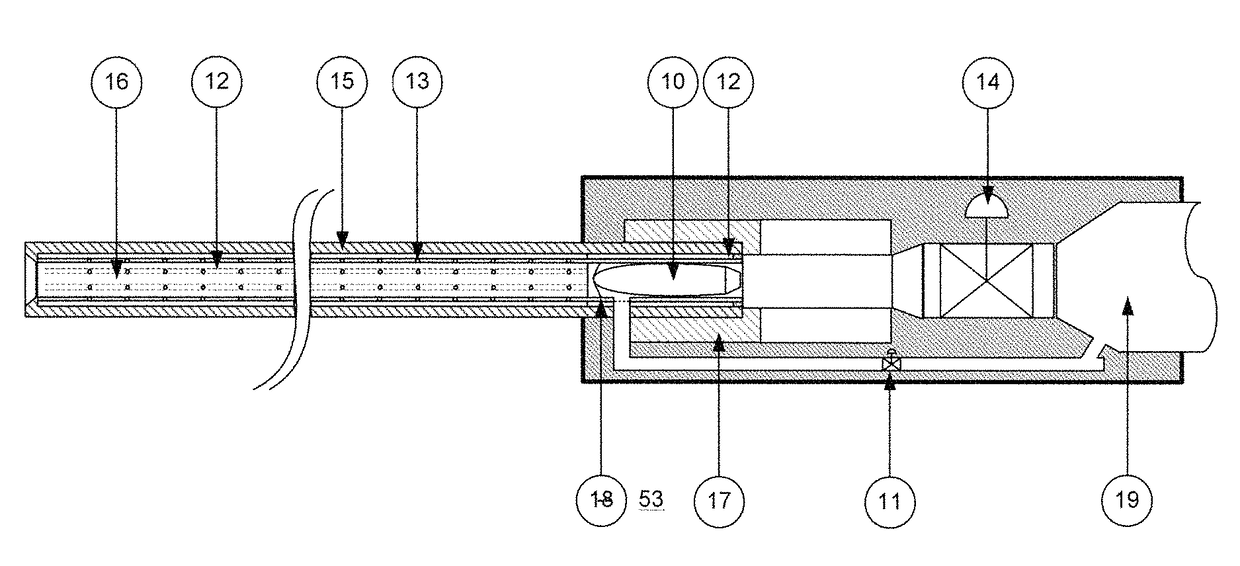
[0060]The projectile 10 is loaded into the breech assembly FIG. 4 by opening the receiver locking bolt 17, inserting the projectile 10, then closing and locking the receiver locking bolt 17. With the projectile 10 loaded, the trigger signal is activated, first opening the purge valve 11 for sufficient time to purge the barrel of air and replacing it with light gas, then the trigger valve 14 is opened and the purge valve 11 is closed simultaneously. Light gas entering the breech 38 through the trigger valve 14 from the light gas source 19 propels the projectile 10 down the barrel. A light gas pressure wave also travels the channels 12 on the outside of the inner tube 15 and enters the inner tube 15 through the gas bearing ports 13, creating a vortex in the barrel that imparts a spin on the projectile 10 as it travels down the barrel. The light gas travels the channels 12 faster than the pressure wave behind the projectile 10, allowing the light gas to flow through the gas bearings to...

second embodiment

[0061]The second embodiment is identical to the first with one exceptions. The channels 12 and gas bearing ports 13 are cut and drilled normal to outside wall of the inner tube 15, for projectiles that do not require spin stabilization.

[0062]The light gas gun's other mechanisms, the frictionless barrel FIG. 2A, the purge and trigger valves 20 / 14 all operate identically to those in the first embodiment.

third embodiment

[0063]In the third embodiment, the necessity to purge the barrel assembly FIG. 2B is eliminated by adding a muzzle valve assembly FIG. 3 on the muzzle end of the barrel assembly FIG. 2B. The muzzle valve assembly FIG. 3 has an opposing multi-leaf valve 28 that allows the projectile 10 to exit the light gas gun while maintaining a positive pressure in the light gas gun after firing. The muzzle valve assembly FIG. 3 also has a plurality of muzzle vent valves 28 that vent excess pressure through a suppression canister 25 to maintain a fixed positive pressure in the frictionless barrel and breech assemblies FIGS. 2B and 4. Venting excess gas through the suppression chamber 25 significantly reduces the acoustic signature of the light gas gun.

[0064]The muzzle valve 23 as shown in FIG. 1C is an opposing multi-leaf valve 28, as shown in FIG. 3, where the actuators 32 move the leaves 38 to a position where the leaf bores 36 align with the barrel assembly bore as shown in FIG. 3B. The muzzle ...


PUM


Abstract

An improved light gas gun launches a projectile in a light gas atmosphere as it travels through a frictionless barrel to achieve high muzzle velocities, decreased acoustic signatures, and increased ranges. The light gas atmosphere is introduced by a purge valve prior to firing or by a muzzle valve that holds a positive light gas pressure on the barrel and breech. The muzzle valve also routes the majority of propellant gases through a suppression canister, reducing the light gas gun's acoustic signature. The frictionless barrel uses light gas propellant routed through gas bearings to keep the projectile centered in the barrel and preclude the projectile from contacting the barrel walls, eliminating barrel wear.

Description

BACKGROUND OF THE INVENTIONField of the Invention[0001]This invention relates to a means for propelling a projectile at relatively high muzzle velocities using light gas as the working fluid and increasing range and lethality while minimizing visible and acoustic signatures.Description of the Prior Art[0002]Hypervelocity guns have been used since the late 1940s for impact and strength of materials research. These guns use light gases, primarily hydrogen, as the working fluid to propel projectiles at speed ranging from 5 to 30 thousand feet per second. Much of the development of the guns is centered on improving the light gas propellant delivery to the breech. Single stage, two stage, and three stage pistons schema have been proposed, most with the intention of ever higher muzzle velocities.[0003]Koth, U.S. Pat. No. 7,954,413, proposes an improved two-stage light gas gun for launching projectiles at high speeds. The gun consists of three tubes: the expansion, pump, and launch tubes. ...

Claims


Application Information

Patent Timeline
Patent Type & Authority Patents(United States)
IPC IPC(8): F41A1/04F42B6/10F41B11/73F41B11/723F41B11/68F41A21/28F41A21/02
CPCF41B11/68F41A1/04F41A21/02F42B6/10F41B11/723F41B11/73F41A21/28
Inventor BERGERON, DAVID WAYNE
Owner BERGERON DAVID WAYNE
Why Eureka
Try Eureka