Method and a connecting system for the joining of moulded parts

a technology of connecting system and moulded parts, which is applied in the direction of threaded fasteners, screwing, manufacturing tools, etc., can solve the problem of more labor-intensive methods than punch rivet methods, and achieve the effect of high load-bearing capacity

Active Publication Date: 2018-02-20
AIRBUS OPERATIONS GMBH
View PDF7 Cites 0 Cited by
  • Summary
  • Abstract
  • Description
  • Claims
  • Application Information

AI Technical Summary

Benefits of technology

[0006]An object of the invention is to create a method and a connecting system for the joining of moulded parts, which removes the disadvantages cited above and enables a joint that has a high load-bearing capacity.
[0008]The inventive method enables the implementation of a joint with a higher strength compared with that of a conventional punch rivet process, since the locking collar pin is simultaneous engaged with a plurality of locking grooves, or threaded sections. In that the locking collar is locked together with the locking collar pin by means of radial pressure or a screwing force, and not by means of an axial, or essentially axial, upsetting force, as in the case of the above-cited DE 10 2010 000 500 A1, the locking collar in the locking operation is not upset, or is virtually not upset, and its height before the application of pressure corresponds, or virtually corresponds, to its height after the application of pressure. Since the locking collar pin is itself driven through the moulded parts and the punched hole that accommodates it is thus formed automatically, there is no initial perforation operation. Thus in the inventive method the advantages of a locking collar pin—high strength—are combined with the advantages of punch riveting—no initial perforation operation. Here the term “radial” means not only exclusively, but also primarily, or essentially, in the radial direction.
[0010]The punching section enables execution of a high-quality punching operation, that is to say, the formation of a precise punched hole, and the avoidance of any unwanted deformation of the moulded parts in the edge region of the punched hole. Moreover the punching section enables execution of the punching operation with a minimal punching force. The fact that the locking collar extends over at least two adjacent locking grooves in the axial direction, or over at least two adjacent threaded sections in the axial direction, allows the formation of a multiplicity of undercuts, and thus a high strength for the joint. Here, in contrast to the locking grooves, the external thread enables the locking collar to be unscrewed. In particular when opening the joint the locking action can be quickly and easily released by unscrewing the locking collar.
[0012]For purposes of reducing the complexity of the device the locking collar in one example of an embodiment has a cutting edge. Such a locking collar can be used as a cutting die and immediately after the punching operation can be squeezed onto the locking collar pin by the application of radial pressure, or screwed onto the latter. A tool change for the application of radial pressure by the locking collar is therefore not necessary.
[0013]In an alternative example of an embodiment, the cutting edge is formed on a shaping projection on the periphery of the end face of the locking collar. The shaping projection allows the use of the locking collar as a shaping die and the latter can likewise, immediately after the punching operation, be radially squeezed, or screwed, onto the locking collar pin. A tool change for the application of radial pressure by the locking collar is therefore also not necessary in this example of an embodiment. The shaping of the locking collar-side moulded part thereby causes strain hardening of the same in the region of the punched hole, and thus leads to an increase in the strength of the joint.

Problems solved by technology

However, by virtue of the separate perforation operation before the riveting process, this method is more labour-intensive than the punch rivet method.

Method used


Image

  • Method and a connecting system for the joining of moulded parts
  • Method and a connecting system for the joining of moulded parts
  • Method and a connecting system for the joining of moulded parts

Examples


Embodiment Construction

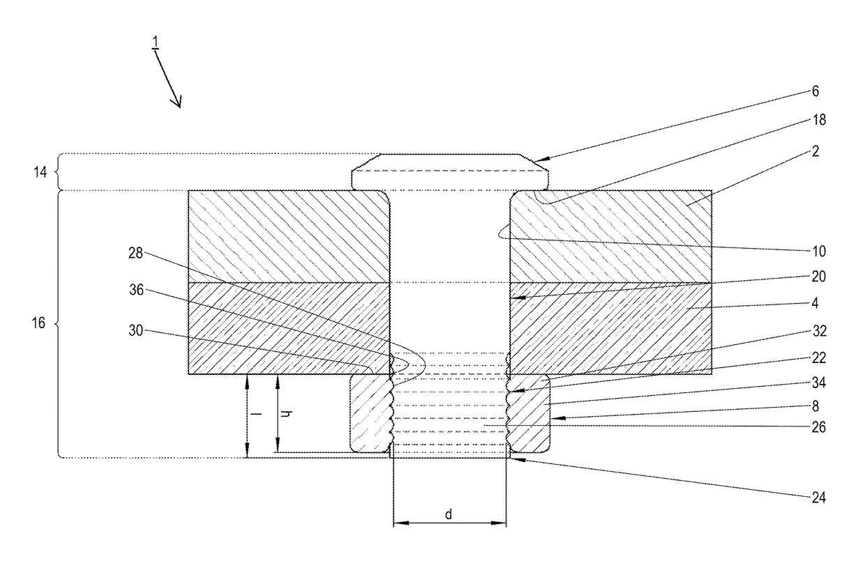
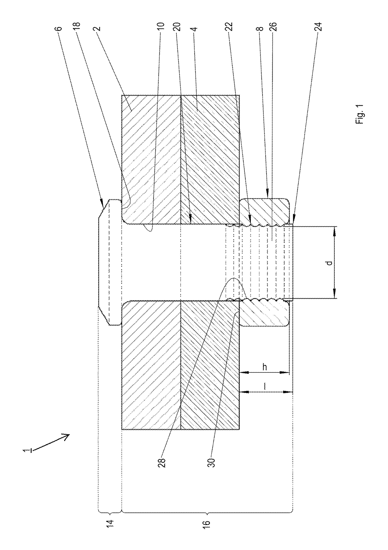
[0022]FIG. 1 shows a joint 1 between two moulded parts 2, 4 with a first example of an embodiment of an inventive connecting system. Needless to say, more than two moulded parts 2, 4 can also be joined with the inventive connecting system. The moulded parts 2, 4 are designed in the form of plates in the region of the joint 1, and in each case preferably are made of a material that can be cold formed such as aluminium, magnesium, steel, or an appropriate metal alloy. However, the moulded parts 2, 4 can also be manufactured from non-metallic materials that are suitable for punching operations such as wood, or a fibre composite material, which for example has a multiplicity of plastic, natural, or metal fibres embedded in a plastic matrix, or a metal matrix. The connecting system has a locking collar pin 6 and a locking collar 8. The locking collar pin 6 is sectionally led out through a punched hole 10 extending through the moulded parts 2, 4, and at its end is locked with the locking ...


PUM

PropertyMeasurementUnit
strengthaaaaaaaaaa
shear strengthaaaaaaaaaa
forceaaaaaaaaaa

Abstract

A method for the connection of moulded parts, wherein a locking collar pin with locking grooves or with an external thread, is driven through the moulded parts and subsequently a locking collar is locked together with at least some of the locking grooves, or with threaded sections of the locking collar pin, by the application of radial pressure, or by means of a screwing operation. A connecting system with a locking ring pin, which has a punching section for purposes of punching through the moulded parts, and also locking grooves for purposes of active engagement with a locking ring; the latter extends over at least two adjacent locking grooves in the axial direction, or over at least two adjacent threads in the axial direction.

Description

CROSS-REFERENCES TO RELATED APPLICATIONS[0001]This application claims the benefit of U.S. Provisional application 61 / 610,501 filed Mar. 14, 2013 and German patent application No. 10 2012 204 015.3 filed Mar. 14, 2013, the entire disclosures of which are incorporated herein by way of reference.BACKGROUND OF THE INVENTION[0002]The invention concerns a method and a connecting system for the joining of moulded parts.[0003]A method of known art for the joining of moulded parts is so-called punch riveting with a solid rivet. Punch riveting often finds application in automotive construction and more generally in the sheet metal processing industry on thin sheets of a very wide variety of metallic materials. Suitable materials are, for example, light metals such as aluminium and magnesium, or ferrous metals such as steel. However, punch riveting also allows the joining of a metallic moulded part to a plastic-based moulded part and thus the manufacture of hybrid joints. By virtue of the rela...

Claims


Application Information

Patent Timeline
Patent Type & Authority Patents(United States)
IPC IPC(8): F16B39/00F16B19/05F16B19/08B21J15/02B21J15/36F16B5/04B29C65/00B29C65/56
CPCF16B39/00B21J15/022B21J15/025B21J15/36F16B19/05F16B19/086Y10T29/5377Y10T29/49948F16B5/04B29C66/7212B29C66/721B29C65/562B29C66/02242B29C66/1122B29C66/21B29C66/41B29K2305/00B29K2301/00B29K2311/00
Inventor BENSE, ROLFGORR, EUGENJENDRNY, JOERGSTROHBACH, TIM
Owner AIRBUS OPERATIONS GMBH
Why Eureka
Try Eureka