
Organic electroluminescent device

a technology of electroluminescent devices and organic materials, which is applied in the field of organic electroluminescent devices, can solve the problems of reducing registration accuracy, reducing the efficiency of semi-transparent electrodes and capping layers, and reducing so as to improve the coupling efficiency of organic el devices, improve the coupling efficiency of each color, and improve the effect of color purity

Active Publication Date: 2018-01-30
HODOGOYA CHEMICAL CO LTD
View PDF8 Cites 0 Cited by
  • Summary
  • Abstract
  • Description
  • Claims
  • Application Information

AI Technical Summary

Benefits of technology

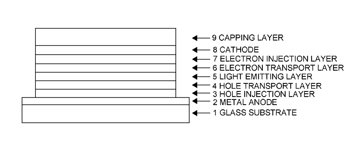
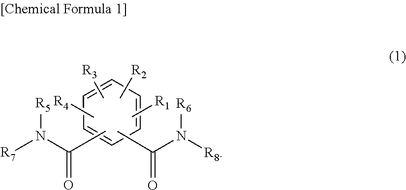
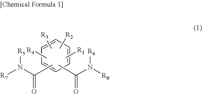
The present invention provides an organic EL device with a capping layer made of phthalic acid derivatives that can improve coupling-out efficiency and be deposited at temperatures of 400°C or less. The capping layer has a higher refractive index than the semi-transparent electrode, and is stable and durable. This material can be used to realize high-efficiency, long-life organic EL devices with clear and bright images and high color purity.

Problems solved by technology

It has also been indicated that maximizing the transmittances of the semi-transparent electrode and the capping layer does not necessarily yield the maximum efficiency, and that the maximum coupling-out efficiency is determined by the interference effect (refer to Non-Patent Document 3, for example).
A problem of such metal masks, however, is that the registration accuracy decreases because of strains due to heat.
In fact, many inorganic materials have high vapor deposition temperatures, and are not suited for use with fine masks, and may even damage the light-emitting device itself.
A capping layer formed by using inorganic materials is also not usable when sputtering is used for the deposition because sputtering damages the light-emitting device.
This is problematic because it lowers the color purity of a blue-emitting device.
Another problem is that the material involves large differences in refractive indices measured in the blue, green, and red wavelength regions, preventing high coupling-out efficiency from being obtained in all of the blue-, green-, and red-emitting devices at the same time.

Method used


Image

  • Organic electroluminescent device
  • Organic electroluminescent device
  • Organic electroluminescent device

Examples


example 1

[0086]The following describes the embodiment of the present invention in more detail using Examples. The present invention, however, is not limited to the following Examples. In the following, “parts” means “parts by mass” in all occurrences.

synthesis example 1

Synthesis of Exemplary Compound 1

[0087]Adamantylamine hydrochloride (7.6 g, 40.5 mM), triethylamine (8.2 g, 81.0 mM), and dioxane (150 ml) were added to a nitrogen-substituted reaction vessel. A dioxane solution (50 ml) of 5-tert-butyl isophthalic acid dichloride (5.0 g, 19.3 mM) was dropped into the vessel while stirring the mixture. The mixture was heated, and stirred at 65° C. for 8 hours. After being allowed to stand overnight, the reaction mixture was added to dilute hydrochloric acid (500 ml) while stirring the mixture. The precipitated crude product was collected by filtration, washed twice with water, and dispersed and washed with methanol twice. The product was dried at 60° C. under reduced pressure to obtain white crystals (9.0 g; yield 96.1%).

[0088]The structure of the obtained white crystals was identified by NMR.

[0089]1H-NMR (DMSO-d6) detected 44 hydrogen signals, as follows.

[0090]δ (ppm)=7.68-7.90 (5H), 2.09 (18H), 1.67 (12H), 1.32 (9H)

example 2

Synthesis Example 2

Synthesis of Exemplary Compound 2

[0091]Cyclohexylamine (12.6 g, 127 mM), triethylamine (13.4 g, 132 mM), and dioxane (300 ml) were added to a nitrogen-substituted reaction vessel. A dioxane solution (70 ml) of 4-tert-butylisophthalic acid dichloride (15.5 g, 60 mM) was dropped into the vessel while stirring the mixture, and the mixture was further stirred for 7 hours. After being allowed to stand overnight, the reaction mixture was added to water (1000 ml) while stirring the mixture. Hydrochloric acid was added until the solution pH was 3, and the mixture was stirred for 1 hour. The precipitated crude product was collected by filtration, water-washed, and dried at 60° C. under reduced pressure to obtain white crystals (22.3 g; yield 96.6%).

[0092]The structure of the obtained white crystals was identified by NMR.

[0093]1H-NMR (DMSO-d6) detected 36 hydrogen signals, as follows.

[0094]δ (ppm)=8.01 (1H), 7.89-7.91 (4H), 3.76-3.81 (2H), 1.85-1.87 (4H), 1.75-1.76 (4H), 1....


PUM

PropertyMeasurementUnit
thicknessaaaaaaaaaa
refractive indexaaaaaaaaaa
voltageaaaaaaaaaa

Abstract

An organic electroluminescent device having a capping layer composed of material having a high refractive index that involves only small differences in refractive indices measured in the blue, green, and red wavelength regions, excelling in thin film stability and durability and having no absorption in the respective wavelength ranges of blue, green, and red is provided to improve device characteristics of the organic electroluminescent device, particularly to greatly improve the coupling-out efficiency.The organic electroluminescent device includes at least an anode, a hole transport layer, a light emitting layer, an electron transport layer, a cathode, and a capping layer in this order, wherein the capping layer contains a phthalic acid derivative represented by the following general formula

Description

TECHNICAL FIELD[0001]The present invention relates to an organic electroluminescent device (hereinafter, referred to simply as “organic EL device”), a preferred self light-emitting device for various display devices. Specifically, the invention relates to organic EL devices that use specific phthalic acid derivatives, particularly to organic EL devices having greatly improved coupling-out efficiency.BACKGROUND ART[0002]The organic EL device is a self-emitting device, and has been actively studied for their brighter, superior viewability and ability to display clearer images compared with the liquid crystal device.[0003]In 1987, C. W. Tang et al. at Eastman Kodak developed a laminated structure device using materials assigned with different roles, realizing practical applications of an organic EL device with organic materials. These researchers laminated an electron-transporting phosphor and a hole-transporting organic material, and injected the both charges into the phosphor layer t...

Claims


Application Information

Patent Timeline
Patent Type & Authority Patents(United States)
IPC IPC(8): B32B9/00C07C233/65H01L51/00B32B19/00C07C233/66C07C233/74H01L51/52H01L51/50H10K99/00
CPCH01L51/005C07C233/66C07C233/74H01L51/0052H01L51/5275C07C233/65H01L51/5253C07C2601/08C07C2601/14C07C2601/18C07C2603/74H01L51/0059H01L51/0072H01L51/5012H01L51/5056H01L51/5072H01L51/5206H01L51/5221H10K85/631H10K85/6572H10K50/858H10K50/844C07C233/64C09K11/06Y10S428/917H10K85/60H10K85/615H10K50/11H10K50/15H10K50/16H10K50/81H10K50/82
Inventor NAGAOKA, MAKOTOHAYASHI, SHUICHITSUJI, MOTONORIAOKI, YOSHIKAZU
Owner HODOGOYA CHEMICAL CO LTD
Learn More